
Loll transmitter and lug gauge design tips
Surface design or tank design designed by the engineer to display various details of surface equipment (flange size, range) in tanks / drums, their height is used as input for mechanical-static engineers (tank) to further engineer tanks .
Why is this provided?
It is prepared as an input document in the mechanical-static section (tank) to be an accurate and documented tool interface.
Who benefits?
These benefits are available to both engineering groups because the details are documented and any changes are tracked by reviewing the document.
Disadvantages / advantages?
Advantages :
For a smaller project, spend less effort than large-scale projects if you do not have a lot of equipment to prepare this document.
Disadvantages:
The interface between the two strings is simplified and there is no room for differences in inputs and information. Changes will always be traceable. If ambiguity is found, this can be documented and corrected.
What are the main inputs required?
- (P&ID (Design level
- (IPDS (Design level
- (Mechanical data sheet (Design level
- (Piping Specification (Design level
- (Instrumentation Design Basis (Design level
- Client / Process Licensor Specific requirements
What are the different types of tanks?

What are the different types of equipment that can be used in tanks?
- Level Transmitter ( Contact / Non-Contact type
- Level – Differential Pressure Transmitter
- Gauge Level (Magnetic, Transparent, Reflex
Various combinations you can have in the tank (standing tube / straight nozzle)
The equipment level nozzle can be installed directly on the tank.
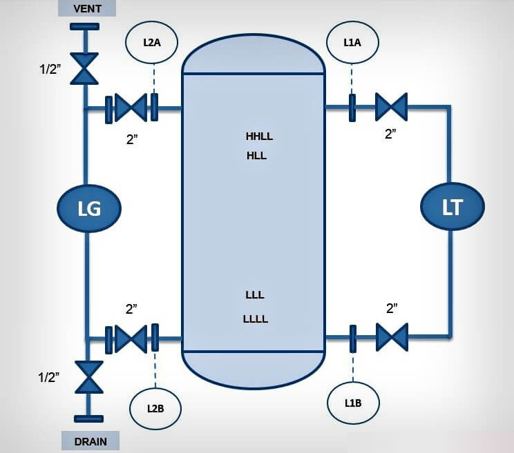
Figure 1 – Surface transmitter and gauge roller are installed directly on the equipment
Standing pipes are used to install surface tools

- Multiple puzzles
- There are no more than 3 devices in the same equipment
- Project specifications
What is all the information to show the equipment?
Equipment details
- Vessel Tag no.
- Nozzle Nos,
- Elevations (in mm preferable
- (Tank Lines (Lower & Upper
- Zero elevation line (either from TL or at other reference point
- Piping Specification, material
Process details
- Process fluid
- Specific Gravity or Density
- Alarm Levels (Low, Low Low, High, High High
- Process & design conditions (Pressure & Temperature
Tool details
- Instrument tag no
- (Type of instruments (Radar, DP Level Transmitter, Magnetic Level Gauge
- C – C (Center to center) distance in mm preferably
- Isolation Valves and sizes
- Drain & Vent valves and sizes
- (Scope Breaks (Instrumentation, Piping, Static
- Traced Lines (Steam / Electrical) / Jacket Lines
- Instrument Nozzle size, connection, rating, Elevations in mm preferably
- Stand Pipe, size and connection details
What not to show
Other than instrument nozzles, other equipment nozzles such as pressure / temperature, inlet, outlet nozzles, nozzle orientation
Example: One level transmitter and one level measurement in a tank


- Service – Water
- HLL = 1400 mm
- HHLL = 1200 mm
- LLL = 350 mm
- LLLL = 300 mm
- Density – 1000 kg / m3, Specific gravity – 1
Low level must be 10% of the transmitter range (subject of project specifications)
The high level should be 90% of the transmitter range (subject of project specifications) so according to the above instructions, different combinations can be used to finalize the transmitter transmitter heights.
Bottom Elevation (HP Tap) : 150 mm (Refer Tip in the above diagram)
Top Elevation (LP Tap) : 1550 mm
Hence CC Distance: 1400 mm
Transmitter Range = (HP Tap Elevation – LP Tap Elevation) * Sp Gravity
Transmitter Range = (1550 mm -150 mm) * 1 = 1400 mm
Hence Select Transmitter Range: 0 – 1400 mm
Calculate LL Level of Level Transmitter
With This, LL level will be at @ 10.7% ie
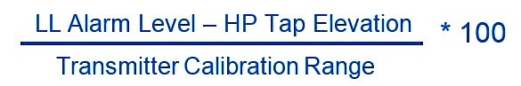
LL Level of LT = [(300 mm – 150mm) / 1400 mm] * 100 = 10.71%
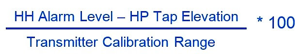
Calculate HH Level of Level Transmitter
And HH Level will be at @ 89.28%. ie