
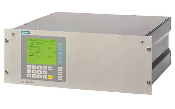
In this article we will discuss about CO analyzer calibration. This article establishes minimum guidelines for performing Trace CO analyzer calibration. This article also allows the instrumentation person to perform basic level configuration and troubleshooting. This paper can be used for CO trace analysis (Siemens Ultramat-6).
- Definition
The trace CO analyzer is based on a micromechanically fabricated Si chip whose measuring aperture contains thin film resistors. The resistors are set at a constant temperature. A current is required to achieve this and its value takes a certain value depending on the thermal conductivity of the sample gas. This raw value is subjected to further electronic processing and is used to calculate the gas concentration. To suppress the effects of ambient temperature, the sensor is housed in a stainless steel housing with thermostatic control.
These are used in the process industry for continuous measurement of CO concentration. It is necessary to calibrate them at regular intervals so that there is no possibility of interlock failure.
- procedural requirements
There are some precautions to follow when calibrating a CO trace analyzer
Safety precautions
- Make sure the necessary tools are used to get the job done.
- If the analyzer is a critical instrument, take necessary precautions to maintain the critical instrument.
- Improper implementation of procedure/execution without proper communication may lead to accidents or cause plant trip.
- Carbon monoxide is suffocating. Carbon monoxide inhalation causes tissue hypoxia by preventing the blood from carrying enough oxygen. Carbon monoxide combines reversibly with hemoglobin to form carboxyhemoglobin. The decrease in blood oxygen carrying capacity is proportional to the amount of carboxyhemoglobin formed. Therefore, it is recommended not to inhale vent gas while cleaning.
- Sample requirement
For best performance, the flow or pressure supplied to the analyzer should be kept at a constant value for both normal sampling and the calibration gas inlet.
Temperature: Min 0 … Max 50 °C, but above dew point
Sample gas humidity: <90% RH (relative humidity), or depending on the measurement task, non-condensing
Conditions: oil free, condensate free, filtered to 2μm
Valve: Each sensor outlet must be connected to a separate atmospheric valve, free of any back pressure. (When choosing the location of the valve, one should pay attention to the toxicity and suffocating nature of the sample gas)
Sample flow: (300 to 1500) ml/min
Allowed sample gas pressure with hose:
Without pressure switch: 600 … 1500 hPa (absolute)
With pressure switch : 700…1300 hPa (absolute)
With tube: 600…1500 hPa (absolute)
(without pressure switch):
- caution
Do not exceed rated current or pressure as sensor damage may occur
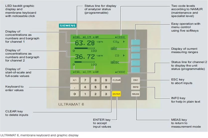
- Display list and function
Calibration method
Proper procedure is essential to ensure satisfactory performance.
- Make sure the calibration routine is ready on the analyzer.
- To perform calibration on the analyzer, ensure the work/maintenance permit application form.
- Place the analyzer in CAL mode by changing the position of the selector switch from Run to Cal on the analyzer panel.
- Connect zero gas cylinder (Zero GR N2) and orifice gas cylinder (8 to 10) ppm CO, Bal N2 and ensure corresponding sample strips.
- Open the zero gas cylinder and adjust the set pressure to 0.5 bar (maximum) and line it up to sample the analyzer.
- Adjust the flow in the rotameter in the range (500 to 1500) mL/min.
- Now clear the analyzer for some time to stabilize the displayed value.
- If a significant difference in the zero value is observed, continue the calibration. Enter the main menu with the help of the function key and enter the code 222 as shown in the general screen above (general display).
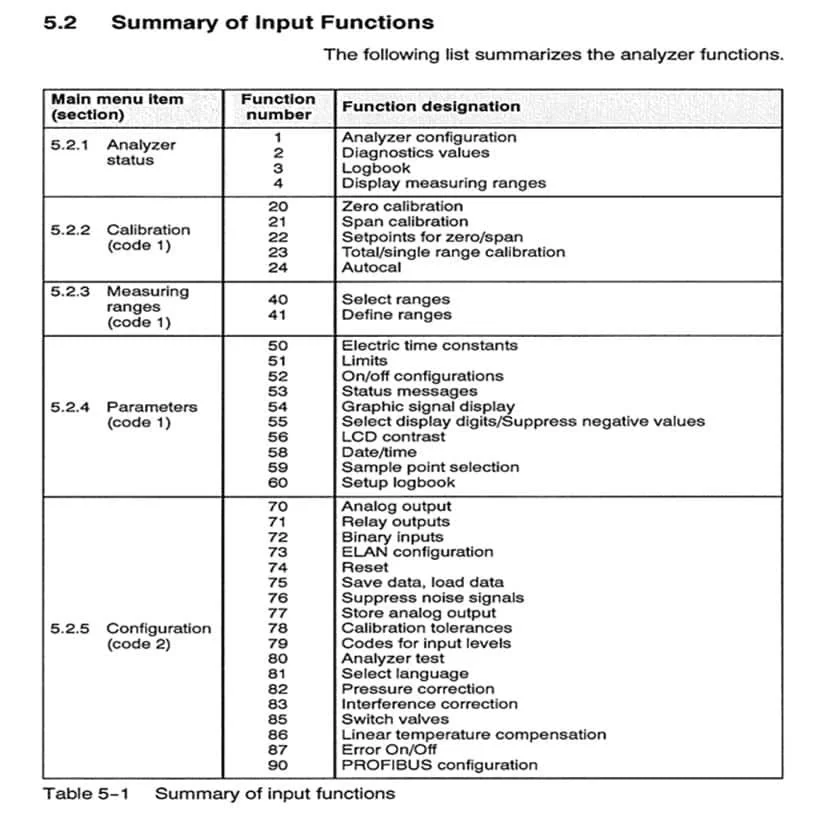
- To change the target value for calibration zero, go to function – 22. Once the target value is entered, select Function – 20 to proceed for zero calibration. See the list of functions for more guidance. (list of functions)
- Now press the corresponding function key to start the calibration.
- Zero calibration is in progress and wait for some time until the measured value is equal to the target value.
- Zero calibration is now complete.
- Release the pressure by moving the regulator handle counterclockwise and close the zero gas cylinder using the cylinder key.
- Open the span gas cylinder, set the pressure to 0.5 barg (maximum) and place span gas in the analyzer line.
- Adjust the flow in the rotameter in the range of 500 to 1500 mL/min.
- Clean the analyzer with the same gas for some time and observe the amount in the analyzer until it becomes stable.
- If a significant difference in the aperture value is observed, calibration is performed. As shown in the general display above (6General Display), enter the main menu with the help of the Function key and enter the code 222.
- To change the target value for aperture calibration, go to function – 22. After entering the target value, select Function – 21 to continue the Span calibration. See the list of functions for more guidance. (list of functions)
- Now press the corresponding function key to start the calibration.
- Aperture calibration is in progress and waits for some time until the measured value equals the target value.
- Orifice calibration is complete.
- By moving the regulator handle counterclockwise, release the line pressure and close the opening gas cylinder using the cylinder key.
- Now take the process sample inline to the analyzer.
- Take the analyzer out of CAL mode
- Allow the task back and close the task.
- Record keeping
The analyzer calibration checklist and calibration record must be completed before and after calibration.
The calibration checklist must be signed by the relevant authority and recorded in the preventive maintenance file.