
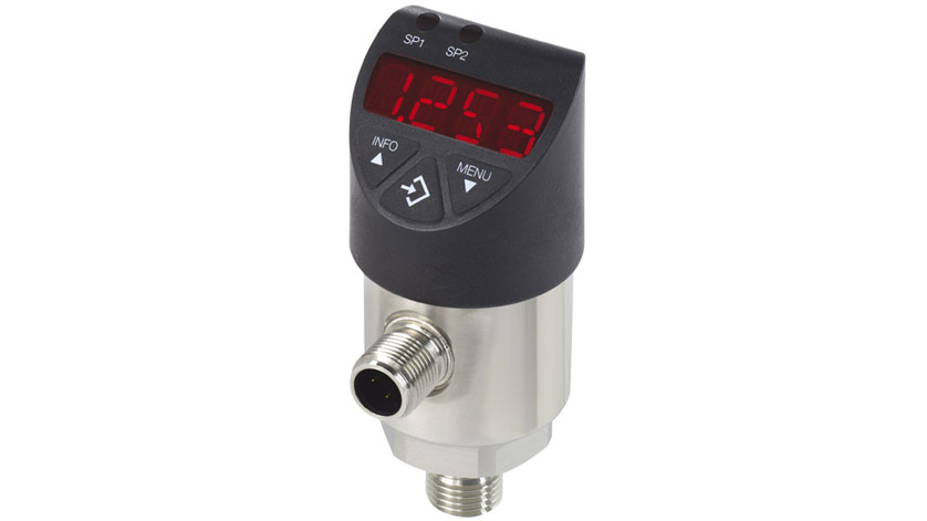
What is a digital pressure switch?
In many systems, mechanical pressure switches are replaced by electronic versions. These digital pressure switches offer a variety of additional features such as a digital display and the ability to adjust switch points electronically. Digital pressure switches are mainly based on electronic pressure transmitters . This switch provides the full function of a transmitter. Simple control tasks can be performed using the integrated pushbutton. Switching points can be set individually using a digital display or I / O link.
Dear ones, you can get more information by referring to the article Gage -e-Pashtar…, or contact the specialized team of E-Shop Sanat for specialized advice.

Principles of digital pressure switch measurement
Digital pressure switches are required to detect pressure (changes) and convert them with high accuracy into an electrical signal. An electrical signal is used to indicate the amount of pressure (change).
The four principles of measuring a digital pressure switch are described below:
Resistance pressure measurement
Resistance pressure measurement uses the resistance of conduction-dependent electrical conductors. This principle makes it possible to create pressure-dependent deflection with electrical resistance. For this purpose, the following relation is applied:
R = ρ * l / A
R: Electrical resistance
Resistance: p
Length: I
Cross section: A
If the length of a conductor increases due to tensile force, the cross section decreases. The electrical resistance is proportional to the cross section. This means that the electrical resistance increases as the cross section decreases. Pressure sensors that use this principle usually have a diaphragm with four metal strain gauges on it. They are distributed in the stretching and compression zones. Therefore, the resistance varies according to the deflection (compression or elongation) of the diaphragm. Wheatstone measuring bridges are used for accurate measurements.

Figure 1: Principle of resistance pressure measurement
Piezzo-resistance pressure measurement
The principle of measuring piezo-resistance pressure is similar to the principle of measuring resistance resistance mentioned earlier. However, the principle of piezoelectric resistance uses semiconductor materials. In addition to changes in cross section, their resistance will change due to deformation, this effect is called piezoelectric resistance. This effect is negligible for conducting metals, but it has a significant effect on semiconductors such as silicon. These semiconductor materials are located inside the diaphragm. This allows both the diaphragm and the barometer to be made of the same semiconductor material. Usually four pressure gauges are installed and connected to a Wheatstone bridge. Semiconductor materials are not suitable for a wide range of media. For this reason, censorship should be protected. This is done by transferring pressure indirectly to the semiconductor using a metal membrane and an oil-like transfer medium. One advantage of piezo resistive pressure sensors is that they can be used for very low pressure ranges. One drawback is the strong dependence on temperature and construction-related changes. This requires that each sensor must compensate for the temperature.
Capacitive pressure measurement
This principle is based on measuring the capacitance of the capacitor. The capacitance of a two-plate capacitor is calculated using the following equation:
C = ε * A / d
Capacity of two-plate capacitor c: Permissibility ε: Separation of plates d: Cross section: a This principle is achieved by using two plates. Deviation due to pressure changes leads to a change in separation between the plates. Due to the constant level and allowable amount, the capacity depends only on the separation of the plate. This leads to high sensor sensitivity. This makes capacitive pressure sensors of suitable amplitude or very low pressure (single mbar range). Excessive safety for the sensor can be ensured because the moving aperture can be deflected to a fixed screen.
 Figure 2: The principle of capacitive pressure measurement
Piezoelectric pressure measurement
Note this is a different principle from measuring piezoelectric pressure. This principle is based on the piezoelectric effect of some non-conductive crystals, such as monocrystalline quartz. Due to the applied pressure or tensile force, the opposite surfaces of the crystal are charged positively and negatively, respectively. This is due to induced displacement in grid elements that have an electric charge. Displacement creates an electric dipole torque that is responsible for surface loads. The voltage difference between the surfaces is measurable and can be converted to a pressure change. Piezoelectric pressure measurement is only suitable for measuring dynamic pressure. These sensors are limited to specific applications.
 Figure 3: The principle of measuring piezoelectric pressure
Types of sensors
The principles of measurement mentioned earlier can be found in three main types of sensors. Thick film and ceramic and thin film sensors are most used to measure the resistance pressure. The third sensor is the piezo resistive pressure sensor.
Thin metal film sensor
The aperture and main housing of a thin metal film sensor are made of stainless steel. Barometers, insulation layers, conductive paths and compensating resistors are applied along the diaphragm that do not come into contact with the environment. Thin film sensors are made in clean room conditions and sometimes in a vacuum. Thin film sensors are very stable due to the materials used. In addition, they are very resistant to shock and vibration. This makes them very suitable for dynamic loads. Due to the weldable material, thin film sensors can be welded to the system connection without further use of sealing material. Due to the ductility of the steel, the sensor has a very low pressure range but a high burst pressure.
Thick ceramic film sensor
The main body and aperture of the thick film sensor are made of ceramic. The most commonly used ceramic is aluminum oxide (Al2O3) due to its processing and stability. Four pressure gauges are applied to the diaphragm that do not come into contact with the environment. They are used as a dough with a thick layer, hence the name. The dough burns at a high temperature in the diaphragm and then receives a protective coating. Thick ceramic film sensors are made in a clean room. Ceramic is very resistant to corrosion, the extra seal required is not resistant to all environments. It is a brittle material, which results in lower blast pressure than thin-film sensors.
Piezo resistance sensor
Piezzo-resistant sensors have a much more complex structure than the previously mentioned sensors. The sensor itself is made of silicon chip. This silicon chip contains a diaphragm in which piezo resistors are placed. The surface of these chips is a few square millimeters, which is much smaller than the apertures of thin or thick film. The piezo resistance chip must be encapsulated due to its sensitivity to environmental influences. This is done by installing a chip in the case of stainless steel. This case is sealed using a thin stainless steel diaphragm. The free volume inside the case is filled with transfer fluid. This fluid transmits pressure from the outer steel diaphragm to the inner sensor diaphragm. Special displacement bodies are used to minimize the effect of fluid thermal expansion on the measurement. A header is used to install and connect the sensor electrically. The header can be welded crosswise to the chamber. Band wires are used to connect the sensor to the pins. A ventilation tube is located in the center of the header and leads to the rear of the sensor diaphragm. Absolute pressure can be measured when the chamber behind the sensor is emptied and the ventilation pipe is closed. In the case of an open vent, the relative pressure is measured. The ventilation pipe is connected to the environment through an external cover or ventilated cable. The ventilation pipe must be protected from contamination, especially moisture.
 Figure 4: Piezo resistance sensor
Chart with sensor applications and technologies
The diagram below shows the various measurement applications with the best sensor technologies. Digital pressure transmitters are cost-effective if you need and control a large number of monitoring points.
