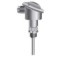
Disadvantages of using RTD
Disadvantages of using RTD: Temperature sensors (RTD) are sensors that are used to measure temperature (temperature measurement sensor). Many RTD elements are made of fine-grained wire wrapped around a ceramic or glass core, but other structures are used. RTD wire is a pure material, typically platinum, nickel or copper. This material has a precise resistance and temperature that is used to indicate temperature. Because RTD elements are fragile, they are often placed in protective probes.

The following are the most important disadvantages of resistance temperature detectors:
Self heating
In order to measure the signal, heat energy is generated while using current to excite the RTD element. The self-heating that occurs causes an error in the temperature measurement. Because RTD changes its resistance in response to temperature, the most practical way to measure it is to pass current through it and measure the resulting voltage drop.
Unfortunately, this excitation current that passes through the resistance of the element increases the temperature of the element, because it tries to eliminate this electrical energy through heat and adds an error to the temperature measurement. The way to deal with the positive change caused by your heating is to increase the thermal contact with the materials we feel, or to reduce the excitation current. The self-heating of an RTD sensor is more pronounced in mW / ° C, which refers to the power required to raise the internal temperature by 1 ° C. Therefore, the higher this figure, the lower the heating itself. For example, suppose 2mA of excitation current is used to drive a 100Ω RTD at 100 ° C.
This produces a sensor resistance of 138.5Ω. Its self-heating profile is 50mW / ° C in water, which moves at 1 meter per second. Therefore, the amount of heat generated by these settings is 1000mW / W * I2 * R = 1000 * (0.002A) 2 * 138.5Ω = 0.55mW. This result is only in a self-heating error (0.55 mg) / (50 mW / ° C) = 0.01 ° C. It is important to note that the effective heating of an element itself depends on the moderate amount to which it is immersed. For example, an RTD can heat 100 times higher in calm air 100 times higher than the moving air it uses.
Because we measure the resistance of RTD by drawing current through it, the I2R power lost by RTD causes the element itself to heat up. Self-heating alters the RTD resistance and increases the measurement error. The negative effect of heating can be minimized by providing a low excitation current. Some devices use RTD excitation currents of up to 0.1 mA to minimize this error.
In the example above, this can reduce the autonomy to 1 0.001mW / 50mW / ° C = 0.00003 ° C, a small amount, even in calm weather. The magnitude of this error is inversely proportional to the capacity of the sensor element to dissipate heat. It is a product of materials, constructions and its environment.
Small RTD elements have higher autothermal effects because they have smaller surface areas that cause heat loss. Perhaps the worst case scenario is RTD with thin film, which typically has a high heat resistance and a small intermittent surface area to dissipate heat. Typically, a dissipation constant is provided in the RTD sensor specifications.
This number corresponds to the power required to raise the RTD temperature by one degree. Thus, a waste constant of 25mW / ° C indicates that if the I2R power loss at RTD is 25 MW, the RTD heats up by 1 ° C. Excretion rate is usually determined by two conditions: open air and a well-stirred oil bath. This is due to the difference in the capacity of the environment to transfer heat from the device. The energy lost from RTD is lost and the dissipation is fixed, you can use your heating temperature increase:
ΔT = P / PD
Where ΔT = temperature increase due to self-heating in degrees Celsius;
P = power dissipated in RTD from circuit in W;
And PD = RTD dissipation constant at W / ° C.
Summary of Disadvantages of RTD Temperature Sensor
Self-heating errors are caused by the inability of the RTD element to dissipate heat from the required power applied through the measuring current. The ASTM standard has a maximum of 1 ° C when using 33 MW in 25 ° C water, the IEC requires a maximum error of 0.05 ° C in 25 ° C water when using the maximum operating current. These test methods are suitable laboratory comparison methods for PRTs that are installed with a suitable collapse in a process, the operating current is 1 mA or less, so the power (I2R) for a 100 Ω PRT is also low (0.02-0.39 MW). ). In sensors with a resistance in the range of 500-1000 Ω, ledger errors may occur or when this process indicates poor heat transfer conditions such as still air or low pressure gases.
Rose Calibration Company in Melbourne, Australia with over ten years of experience provides all calibration, maintenance, and repair services throughout Australia. If you live in Sydney, Melbourne, Adelaide, Perth, Geelong, and Brisbane, you can receive your quote in less than two hours by fill-up the form via the “Booking” link.

