

Frequency calculation in thermowell
Frequency Frequency Calculation : A wake frequency calculation is used to determine or prove the proper dimensions of a thermowell based on process conditions. The thermowell has a specific frequency, which is a function of the thermowell diameter and fluid velocity. If the Wake frequency coincides with the normal frequency of the thermowell, the thermowell vibrates and leads to degradation
Thermol
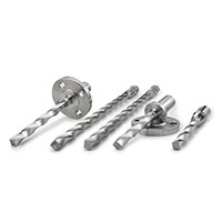
Thermowells are commonly used with thermocouples , RTDs , and temperature gauges in applications where temperature measurements at high pressures (above 75 psig) are used. They are also used for isolation, so a sensor can be replaced without having to turn off the process. Thermowells are machined from different materials. Safety pressures depend on the thermowell material, operating temperature and average flow rate
Frequency calculation in thermowell
As the fluid passes through a thermowell, a change in fluid motion causes a turbulent wake behind the thermowell. Vortices are formed in this state, and pass through the alternating sides of the thermowell. The frequency of the vortex (or Wake frequency) is linear with the velocity of the flow and inversely proportional to the diameter of the thermowell tip.
These wake vortices are imposed on the thermowell, a periodic force consisting of two components – (i) an elevator force, normal to the direction of flow, oscillation at the waking frequency, and (ii) a smaller tensile force, parallel to the current, doubling in oscillation. Wake frequency These forces caused by the vortex, which cause the thermowell to vibrate, are usually very small with the magnitude of the vibrations.
However, as the Wake frequency (fw) approaches the normal frequency (fn) of the thermowell (at 20%), it can switch to the normal frequency and lock. When fw = fn, the thermowell resonates, and the vibration forces increase rapidly.
The resulting vibrations can cause mechanical damage to the well. Murdock calculations (and with ASME PTC 19.3) consider the only oscillating lifting force to be the cause of the thermowell vibration. The wake to normal frequency ratio is limited to a maximum of 0.8 to eliminate the possibility of resonance. Although the oscillating tensile force is small, it can accelerate the thermowell at low speeds because it occurs at twice the Wake frequency.
For high density liquids (high pressure liquids and vapors), Murdock analysis is not sufficient. When the oscillating drag component is included, the speed rating can be reduced by up to 50%. The calculations here have been modified to include in-line resonance due to the oscillating tensile force, correction of the magnification ratio, and the use of the actual natural frequency of the well, not the estimated value. The results of these calculations should only be used as a guide in choosing the correct thermowell. Other variables such as corrosion must be evaluated and influence the decision.
Thermowell speed calculations
As liquids pass through the thermowell, low-pressure vortices form downstream of the well. These vortices are poured from different sides of the well, and the resulting differential pressure creates two periodic forces on the thermowell:
- An oscillating lifting force, transverse to the fluid flow at frequency fs
- An oscillating tensile force, corresponding to the fluid flow at the vortex frequency 2fs can occur at frequencies from 50Hz to 1500Hz. The Strouhal frequency increases linearly with the velocity of the fluid, but the forces increase with the square velocity. When the Strouhal frequency approaches the normal frequency of the thermowell, it can enter the natural frequency that causes the resonance with very large forces. To prevent locking, the normal frequency of the thermowell should be higher than the line mode or transverse fluctuation. Performance through in-line resonance is acceptable only if the cyclic stresses under acceptable resonance conditions are small. The velocity of the fluid at which the resonance occurs is called the critical velocity. There are two velocity frequencies for each normal thermowell frequency: one describes the transverse and the other describes the inline response. Since the in-line force fluctuates at twice the frequency of the transverse force, the corresponding critical velocity is approximately half of that required for transverse amplification. If the normal frequency of the thermowell also overlaps with fs or 2fs, a large increase in resonance in the vibration amplitude may occur. The main cause of thermowell failure is resonant fatigue.
A sufficiently high damping level may cause the thermowell to operate at in-line frequencies or even transverse resonance. In addition to frequency limitations, the stresses within the thermos and the forces applied are also critical to assessing the suitability of a thermostat for a particular process application.
The 4 quantitative criteria that are evaluated are:
1: Frequency limit:
The motor heat resonance frequency should be high enough so that destructive fluctuations are not evoked by the fluid flow. Steady state fluid velocity (s) must meet one of the following conditions:
fs (ss) <0.4 • fn OR 0.6 • fn <fs (ss) <0.8 • fn
2: Static stress limit:
Steady state stresses are the result of hydrostatic fluid pressure and non-oscillating tensile forces on the thermo and are calculated at the point of maximum stress. If the thermowell is partially protective or has a reduced tip, the calculation must be made with those considerations in mind. The maximum steady-state stress on the thermowell at design speed should not be determined from the allowable stress according to von Mises criteria.
3: Dynamic stress limit:
Dynamic stresses are the result of periodic tensile forces that cause in-line oscillations and periodic lifting forces that cause transverse oscillations. If the thermowell is to operate above the critical line velocity, there are cyclic resonance stresses within the line so keep in mind that it passes through that point in the design velocity path. The maximum dynamic stress should not exceed the allowable fatigue stress limit. Magnification factors are calculated and applied in the cyclic stress equations, then the tensile forces and the cyclic lift are calculated at the design speed. Maximum elevator and drag stress should not be too much fatigue stress.
4: Hydrostatic pressure limit:
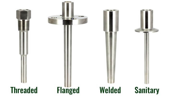
The external pressure must not exceed the minimum pressure of the brake tip, stem or flange (or thread) at operating temperature.
Thermowell standards
ASME PTC19.3-1974 is the standard used for many years to design more thermowells. This standard only applied to cone profiles and did not accommodate the stress of in-line resonance due to oscillating force. ASME PTC19.3TW-2010 is a new standard released in July 2010 to replace the 1974 standard. This method uses more advanced methods to evaluate the suitability of a thermowell for a particular application and can be used for conical, straight and low consumption profiles.
Calculate the waking frequency of the thermowell
Thermowell wake-up frequency calculations are usually done before the thermowell is made. They ensure that the design of the thermowell is strong enough to withstand the various pressures and pressures generated by the process environment. Wake frequency calculation data is available with the following basic parameters:
- Pressure
- Temperature
- Speed
- viscosity
- Density
Any failure of the thermowell will occur at the highest stress point, ie between the flange / shaft connection. With the exception of the use of speed collars (which cause their own problems and are not recommended in current ASME PTC 19.3 TW-2010 standards), this has traditionally meant shortening or enlarging the thickness of the thermowell.