

What is the purpose of hydraulic calculation?
A hydraulic calculation is performed for the pump, compressor, control valve and piping system. These are the most common equipment and tools used in the process industry. The main purpose of hydraulic calculations is to provide criteria and minimum requirements for the selection of pumps, compressors and control valves for the development of the process information sheet. To prepare pumps, compressors and control valves, it is necessary to transfer all process information in the form of a process information sheet to the relevant vendors. If specific instructions are provided in the project specifications, they should take precedence over the requirements set forth in these instructions.
Hydraulic calculations can be done at different stages of a project, for example. In the introductory stage, in the detail engineering stage also after the issuance of isometric drawings.
Hydraulic calculation steps
For hydraulic calculation, a hydraulic circuit must be constructed before the hydraulic calculation. Also, before performing hydraulic calculations, you must collect the required data (see 2.1). You must follow the steps below:
Step 1, select the ring whose hydraulic calculation is to be performed.
Step 2 Mark the hydraulic ring in PFD and then in P & ID.
Step 3, draw the hydraulic ring in the relevant software (because different companies use different software).
Step 4, Any element in which the pressure decreases, such as flowmeter, filter, heat exchanger, dryer, control valve, FO, etc., must be shown in the hydraulic circuit to calculate the end point pressure in each section.
Step 5 Put the flow rate, physical properties, nominal diameter, roughness coefficient, equivalent length, etc. in each section of pipe.
Step 6, run the model.
Step 7, review and evaluate the result of the hydraulic calculation.
2.1 What is the data required for hydraulic calculation?
The data used for hydraulic calculations, such as flow rate, temperature, pressure, etc. should be specified as follows. Design data is obtained from, but not limited to, the following documents.
- Process flow chart (PFD)
- Basic Engineering Design Data (BEDD)
- Plumbing and instrumentation diagram (P&ID)
- Heat and material balance (H & MB)
- Plot design
- Equipment information sheet
- Specifications of plumbing materials
Input data for hydraulic calculation
Below is a summary of the input data that is prepared before the hydraulic design.
(1) Operational data required in hydraulic calculation
- Service to identify
- Fluid name to identify
- From-to to identify
- Liquid and / or vapor flow rate (s)
- Temperatures
- Pressure
- Physical characteristics
For liquid service: density, viscosity, vapor pressure, critical pressure, SpGr @ 15 ° C
For steam service: density, viscosity, molecular weight, specific heat ratio (Cp / Cv)
Compressibility coefficient (Z)
Two-phase flow: density and viscosity for liquid and vapor
(2) Construction data in hydraulic calculations
- Line class
- Height at the inlet and outlet of the piping system.
- Distance between origin and destination
- Let, types and quantities
- Types of valves and fittings, types and quantities.
- Control valve (s)
- Pump (s), compressor (s) and blower (s)
(3) Design requirements in hydraulic calculations
- NPSH pump available
- Over Design percentage – Design flow rate specifications, if any
- Percentage reduction – Specification of minimum flow rate, if any
-
Calculation and hydraulic formula
3.1 General:
(1) As we know, the capacity of pumps and compressors, the power and the need for the head depend on the frictional pressure drop created by the associated piping system. Therefore, in a hydraulic calculation, the entire ring must be created according to P & ID. Pressure losses through the pipeline must be carefully calculated. The main parameters used to investigate are pressure drop and velocity. If in a hydraulic calculation it is observed that the pressure and velocity drop is greater than the limited criteria mentioned in the project criteria, the line size can be increased and subject to the approval of the employer. The basic principle for determining line size should be based on an economic perspective, ie minimizing the total operating and investment costs.
3.1.1 Basic principle for line size used in hydraulic calculation:
(1) The basic principle for stabilizing line sizes during hydraulic calculations should be based on an economic perspective, ie minimizing the total operating and investment costs.
(2) However, the size of the lines should not exceed the limitations provided in the project specifications
(3) In some cases, process requirements take precedence over economic aspects. For example, in the case of pump suction lines where NPSH is the main malware.

Darcy Wiesbach’s equation
Here,
- ΔP = frictional pressure drop
- f = Modi coefficient of friction
- Le = equivalent length
- S2 = unit conversion factor.
(2) For slow flow (Reynolds number below 2000) the coefficient of friction can be calculated as f = 64 / Re, here f = coefficient of friction.
(3) For turbulent flow (Reynolds number above 4000, the coefficient of friction can be calculated using the equation created by the Kohlbrook correlation:
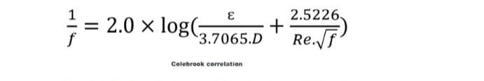
Kulbrook correlation
Where, ɛ = pipe inside the roughness, unless otherwise specified, the roughness of the commercial steel pipe can be considered 0.0457 mm.
Below are the typical fluids in this category.
- General hydrocarbons
- Chemically treated water such as cooling water, boiler feed water and so on.
(4) The Hazen and William experimental formula should be applied in a hydraulic calculation, considering Hazen and Williams as
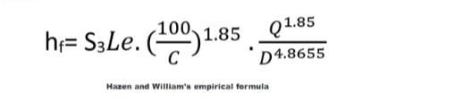
Where
- hf = friction head drop, m
- Le = equivalent length, m
- C = coefficient of friction
- Q = flow rate, m3 / sec
- D = inner diameter of the pipe, m
- S3 = Unit conversion factor, 0.002125
This formula can be used for any liquid with a viscosity in the range of 1.13 cm, which is true for water at 15 ° C. Friction coefficient C = 100, for the following service;
- Seawater flowing through an untreated inner surface pipe
- Oxygenated and chemically untreated water such as drinking water, industrial water, etc. that flows in an untreated inner surface pipe.
(5) Compressible gas flow formulas used in hydraulic calculations
For low pressure drop service: To estimate the pressure drop in short periods of gas piping, the Darcy-Weisbach formula described above is applicable and accurate, assuming that the line pressure drop is not more than 10% of the total pressure. (GPSA Engineering Data Book, Section 10).
For high pressure drop service, in conventional gas piping, the flow is closer to adiabatic than isothermal. Adiabatic flow pressure drop can be calculated using the following equations:
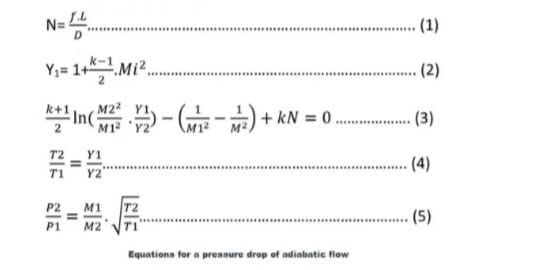
Here,
- P = pressure (N / m2)
- T = Temperature (° K)
- N = pipe resistance coefficient
- u = speed (m / s)
- a = Acoustic speed (m / s)
- M = Mach number = u / a
- Y = Mach number factor
- f = Modi coefficient of friction based on average viscosity
- D = pipe diameter (meters)
- L = pipe length (meters)
- k = Cp / Cv, specific heat ratio (-)
- R = gas constant = 847.9 / molecular weight ((Kgf / m2) ・ m3 / kg-mol ・ ° K)
- Subtitle 1 = input and 2 = output. i = 1 or 2
calculation method
- Step 1: Assume downstream conditions (P2, M2, T2)
- Step 2: Calculate M1 with Equation (3) as the trial and error method.
- Step 3: Calculate T1 with equation (4) with M1 from step 2.
- Step 4: Calculate the pressure drop with Equation (5) with M1, T1 from steps 2, 3.
- Step 4: If the calculated P1 is equal to the given inlet pressure, the calculation can be terminated. If not, go back to step 1 with the new hypothetical conditions.
3.2 Standard Tube Data:
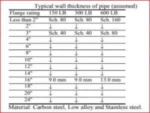
Standard tube data
3.3 Line size limit:
Lines should be measured with the constraints of the table below (see Table 1)
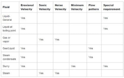
Table 1: Restrictive parameter
3.3.1 Abrasion rate formula used in hydraulic calculations:
(1) The higher rate at which erosion may occur in a two-phase gas / liquid stream can be determined using the following experimental equation. Ve = Ce / √ρm, where, Ve = erosion rate, ρm = homogeneous density, Ce = normal experimental constant in the range 180-240.
(2) Water piping: The maximum speed should be less than the values given below.
- Mortar or concrete 3.0 meters per second
- Mortar primer sealing coating with 5.0 m / s paint
- Steel or PVC cast iron 6.0 m / s
(3) amine solution:
The speed in the amine process should be less than the following.
- Carbon steel
- Liquid 3 meters per second
- Steam 30 meters per second
- stainless steel
- Liquid 9 meters per second
- Steam 36 meters per second
3.3.2 Acoustic velocity formula used in hydraulic calculation:
(1) The maximum speed shall be less than 50% of the sound speed for continuous gas or steam service.
(2) For intermittent services, such as pressure relief valve drain piping, 80% speed may be acceptable. Return pressure limits must be observed.
(3) The speed of sound can be calculated as follows.
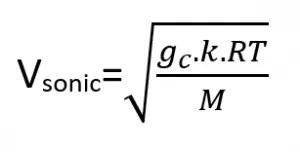
Sound speed calculation equation
Where,
- Vsonic = Sound speed (m / s)
- gc = Gravity conversion factor (kgf ・ m / kgf ・ s2)
- k = specific heat ratio = Cp / Cv
- R = gas constant = 847.9 (kgf / m2) (m3) / (kg-mole) (° K)
- T = Temperature (° K)
- M = molecular weight
(4) When the pressure drop across the valve is relatively large, e.g. Inject steam, nitrogen headers, etc. and check the acoustic velocity for the downstream piping of the valve.
3.3.3 Slurry line:
(1) The minimum and maximum speed cycle cycles for cycle oils containing catalyst particles should be as follows.
- Minimum speed of 1.1 meters per second
- Maximum speed 2.1 meters per second
(2) Other services
If practical, the flow velocity should not be less than 0.9 m / s to minimize solids deposition. [API RP-14E 2.3a – 1991]. The maximum velocity should be less than the erosion rate, which depends on fluids and processes. Therefore the erosion rate will be provided by the process licensee.
3.3.4 Two-phase flow pattern:
(1) The method of estimating the pressure drop and flow pattern for two-phase gas / liquid flow in hydraulic calculations is based on the following:
- Pressure drop: HTFS method
- Flow pattern: TULSA University method
(2) Flow patterns
The flow pattern is determined using a method developed by TULSA University based on the Title and Dockler method. Also, this method is used in HTFS Handbook TM2 (August 1986).
(3) The flow pattern map with definition of coordination is as follows:
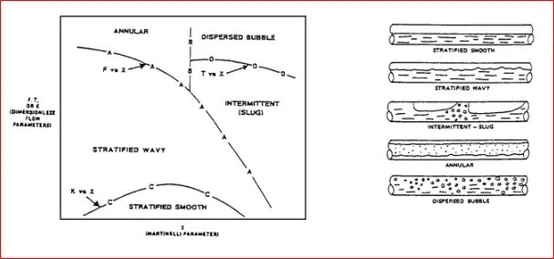
Flow pattern in two-phase flow
The flow pattern is defined as follows:
Bubble flow: The gas phase is distributed as separate bubbles in a liquid chain. Bubbles tend to flow at the top of the tube.
Classified current: Liquid and gas phase separation is complete. Liquid flows at the bottom of the tube and gas at the top.
Wave current: As the gas velocity in the classified stream increases further, surface waves begin to form on the liquid layer.
Spiral current (alternating current): As the gas velocity in the wavy flow region increases further, the waves become so large that they reach the top of the tube. These waves are propagated by gas at high speeds, often foamy in nature and are called “rob”.
Circular flow: As the gas velocity increases more, the nozzles no longer occur and the flow becomes essentially circular but with a thicker layer at the bottom of the pipe than at the top.
3.3.5 Instructions for line size in hydraulic calculation:
The final line size should be determined in the hydraulic calculation. In order to minimize accurate analysis, the following guidelines are useful for practical line measurements. Tables 2 to 4 show the practical pressure drop and the practical speed for each service.
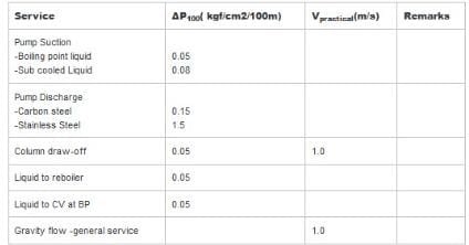
Table 2: Pressure drop and practical velocity for liquid services
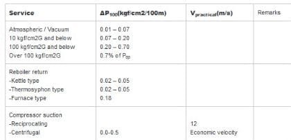
Table 3: Pressure drop and practical speed for gas and steam service
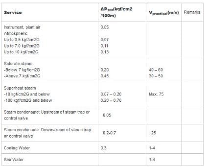
Table 4: Pressure drop and practical speed for municipal services
3.4 equivalent length of piping
3.4.1 Estimation of equivalent length for hydraulic calculation:
(1) Equivalent piping length: If not available, the equivalent length should be taken from the piping design, the length should be taken from the plot map and the equivalent length (Le) of the piping should be estimated on a direct basis. Length (Ls) is as follows:
Process area: 3.0 times direct length (variable based on project specifications)
Lines on the shelf: 1.5 times the direct length for temperatures above 100 ° C and 1.2 times the direct length for temperatures below 100 ° C (variable based on project specifications).
It is recommended to count the number of elbows, tees and valves and evaluate the equivalent length assuming a large size pipe design or high pressure piping.
(2) Pump suction line: When the pipe design is not available, the equivalent length of the pump suction line should be considered at least 50 meters for process pumps and municipal pumps.
(3) Expansion rings: Thermal expansion rings are usually set for long, high-temperature service lines such as the HP steam line and the flame line. Since the expansion rings significantly increase the equivalent length, if the pressure balance is strong in the selected pipe size, confirm the Piping section for the expected numbers.
3.5 Pressure drop data
3.5.1 Pressure drop of the tool for hydraulic calculation:
(1) If an estimated pressure drop is available for the device, use it in hydraulic calculations. If not, use the allowable pressure drop.
(2) If pressure drop data is not available for a tool, the data (for low viscosity service) may be assumed as follows:
- Flow opening 0.2 kgf / cm2
- Venturi tube 0.02 kg per square centimeter
- Rotameter 0.2 kgf / cm2
- Displacement مثبت Positive gauge 0.6 kg / cm2 (page included)
- Turbine meter 0.5 kg per square centimeter (page view)
(3) For high viscosity service (μ> 1cP) or non-Newtonian fluid, pressure drop should be calculated or evaluated from available sources such as vendor information.
3.5.2 Pressure drop of pipe components for hydraulic calculation:
(1) Pump suction filter
The pressure drop of a permanent filter should be considered as follows.
0.5 meters for dirty service
0.3 meters for clean service
3.5.3 Pressure drop of equipment for hydraulic calculation:
If estimated pressure drop data for the equipment are not available, the pressure drop for the low viscosity service may be assumed as follows:
Heat exchangers 0.3 – 0.7 kg / cm2
Air conditioners
0.3 – 0.5 kg / cm2 for clean service
1.0 – 1.5 kg / cm2 for contaminated service
Filters 0.7 kg per square centimeter
3.5.4 Hydraulic calculation of control valve pressure drop:
The following criteria are usually used for the control valve when calculating the hydraulics.
(1) A DP control valve shall be specified as greater than the following values.
- At least 0.7 kg / cm2 on the pump ring
- 8% pump discharge
- [(1.1135 x (maximum flow / normal flow)) 2-1] x ΔP friction, where the ratio of maximum flow to normal flow is too much of a design factor
- 33% of friction ΔP
3.6 Hydraulic circuit and calculation sheet
The following figure shows a hydraulic circuit,
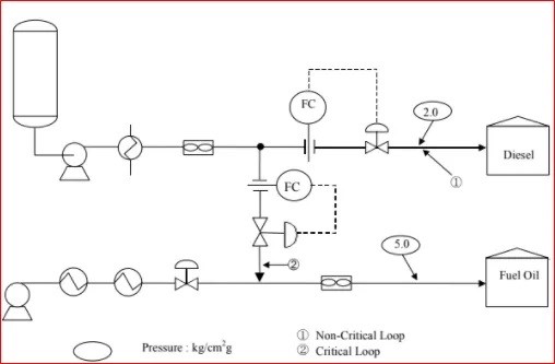
A typical hydraulic circuit
(2) The following data sheets should be prepared as a result of hydraulic calculation.
- Hydraulic flow chart
- Pressure balance
- Flow pattern for two-phase current
(2) The data sheet should contain the following information.
Line size, source equipment (pressure and height), suction and discharge pressure of the pump, equipment in the pump discharge line, inlet pressure and their pressure drop, inlet and outlet pressure of control valve, destination, pressure and height.
(3) The following parameters should be evaluated based on the results of hydraulic calculations.
– Design pressure, operating pressure, line classes, equipment nozzle size, equipment height, etc.
The following figure shows an example of a hydraulic balance sheet.
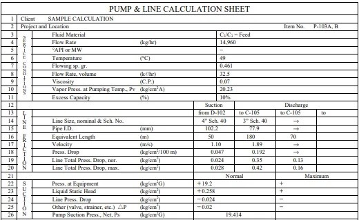
Pump and line calculation sheet
-
Hydraulic calculation software programs:
In the old days, hydraulic calculations were done on Excel spreadsheets. But today, various software has been developed for error-free hydraulic calculations. These softwares also save working hours and make the calculation faster. Common hydraulic calculation software that is widely used in EPC industries are:
- HRS system,
- Hcalc,
- Mansoura is a genius,
- AFT Fathom,
- Haitus,
- Hydrate,
- Flow
- PASS / Hydrosystem,
- Pipent,
- Flowmaster,
- Flonex and so on