

Meet Measuring device VSM magnetic properties
With the advancement of technology in the field of magnets and their wide applications in the field of industry, there is a need for a tool that can be used to study the magnetic properties.Magnetometers There is a difference in this regard based on Current frequency Crossings are divided into several categories. Devices Magnetometer In different ways and under different temperature conditions, the magnetic field and the orientation of the sample measure the magnetization of a sample of material with different dimensions.
The basis of the VSM magnetometer is the Faraday induction law, which, by vibrating the sample and applying a magnetic field to it, creates an inductive current in the coils embedded in the device that is proportional to the sample’s magnetism. By transferring this inductive current to the computer connected to the device and displaying the waste loop, the sample magnetizes measurement Becomes.
Abstract
One of the most important properties of materials is their magnetic properties, which have been considered for a relatively long time and are now in a wide range of industrial applications. Therefore, to study the magnetic properties of materials, devices are needed to measure their magnetic properties, one of the most important of which is magnetometers [1]. Using the magnetometer device, the magnetic properties of diamagnetic materials, paramagnetic, ferromagnetic, anti-ferromagnetic, free magnetic can be examined.
This laboratory device was invented in 1956 by Simon Foner, a professor at MIT, and commercialized by EGG PAR (EGG Princeton Applied Research) in the 1960s [2]. Magnetometers are used to determine the magnetic properties of materials such as magnetic moment and inhibitory field as a function of magnetic field, temperature and time. Materials whose magnetic properties can be measured using a VSM device are: thin films, powders and liquids [3]. To better understand the magnetometer, first the source of the magnetic property, the magnetic phases, and the residual ring, which is a kind of visual expression of the magnetism of matter, are briefly stated.
The origin of magnetism Materials
The source of magnetic properties in solids are moving electrons. Although some atomic nuclei have a permanent magnetic dipole moment, their effect is so weak that it can not have significant effects; Except under certain conditions, such as when the sample is below one degree Kelvin or when it is exposed to an electromagnetic field with a frequency that intensifies the forward motion of the nuclei. With the advent of magnetic theory, many experiments showed that the magnitude of the total angular motion of an electron and its associated magnetic moment was greater than that attributed to its transient motion. Therefore, an additional contribution, which resulted from an intrinsic property with an internal degree of internal freedom, was attributed to the electron, and because this property had a similar effect to the rotation of the electron around its axis, it was called a spin [4].
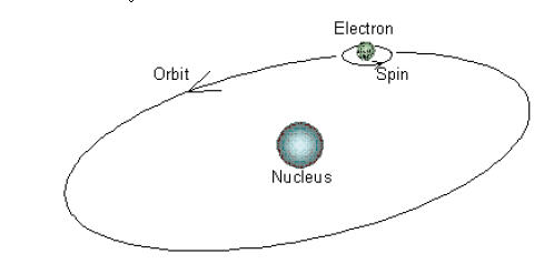
Figure 1. Electron motion around the nucleus
Determining the relative magnetic orientation of electrons in an ion located in a crystal lattice depends on the interaction between the electrons, which in general divides the interactions between the electrons into three categories:
1) Coulomb interaction
2) Spin orbital interaction
3) The effect of the crystal field
3. Magnetic phases:
Materials in the external magnetic field show different behavior and according to the orientation of the magnetization, are divided into several categories:
Paramagnetic materials: These materials are composed of atoms that They have a permanent atomic magnetic moment but act separately and without any interaction on each other, which eventually has a random orientation. Its magnetic direction is positive but small and under the influence of an external field, they are in an approximate direction ( Figure 2 a).
Ferromagnetic materials: Materials that have spontaneous magnetization in the absence of an external magnetic field and, unlike paramagnetism, their magnetic moments interact with each other. These materials, like iron, have permanent magnets or are attracted to magnets, and their magnetization orientation is completely in the same direction (Figure 2b).
Anti-ferromagnetic materials: In anti-ferromagnetic materials, the resulting magnetization is removed in the absence of an external field and its magnetization orientation is such that the total magnetization becomes zero (Figure 2 c).
Free Magnetic Materials: In these materials, the magnitude of the magnetic moments is greater in one direction than in the other, and as a result the net magnetism of the material is not zero, and the saturation magnet of these materials is less than the ferromagnet (Figure 2d).
Diamagnetic materials: Diamagnetic atoms have no magnetic moment and by being in the external magnetic field, they have induced magnetic moment in the opposite direction of the external field and weaken it.
Figure 2- Magnetic phases (5)
3- Waste ring
When a magnetic field is applied to a magnetic material, the magnetization of the environment increases rapidly; As the amount of field applied increases, the acceleration of the magnetization decreases; This decrease in acceleration continues until the magnetization of the medium reaches its saturation value M S [6].
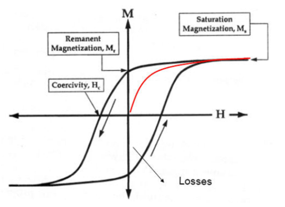
Figure 3 – Waste ring for a ferromagnetic material
Changes in the magnetization of magnetic materials do not follow their previous behavior when the field decreases; Rather, they store some energy due to magnetic anisotropy in the environment. Therefore, when the field of action in the environment becomes zero; The magnetism in matter is not zero and has a special value called the residual magnetization M r . As the field strength decreases further to negative values, the induced magnetic property gradually decreases, and when the field strength reaches a negative value, the magnetic properties of the material completely disappear. This magnetizing field with H CShow and is known as coercive force or magnetic coercion. As the field strength decreases further, the magnetic induction becomes negative and can eventually reach its negative saturation values. Re-increasing the field strength to positive values completes the residue loop as shown in Figure (3). Permanent magnets are often used in the second quarter of their waste ring [7]. The residual or coercive force is an inverse field that needs zero to reduce its magnetism.
Magnetic materials are divided into two groups of soft and hard magnetic materials in terms of their behavior in the magnetic field.
1-3- Soft magnetic
materials Soft magnetic materials are easily magnetized by applying a small magnetic field and quickly lose their magnetic moment by cutting off the field. In other words, these materials have a low coercive force. These materials also have high magnetic saturation M S and low residual torque M r .
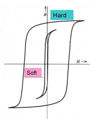
Figure 4. Waste ring in soft and hard ferromagnetic materials
Soft magnetic materials are used where rapid magnetic torque is required by the application of small magnetic fields, such as motors, magnetic heads, sensors, inductors, and acoustic filters.
2-3- Hard Magnetic Materials Hard magnetic materials are
materials that are not easily magnetized by soft magnetic materials and require a larger magnetic field to magnetize them. These materials retain magnetic torque for a long time after the magnetic field is cut off. They also have high magnetic saturation M s , residual torque M r and high coercive force H c . The fabrication or sintering of these materials in a magnetic field increases the magnetic anisotropy in these materials; Which makes the wall of the spheres more difficult to move and increases the coercive force. This can ensure the production of better hard magnetic material. These materials are used in permanent magnets and magnetic memories.
Vibrating Sample Vibrating Sample Manometometer
(VSM = Vibrating Sample Manetometer) is used to measure the magnetic properties of a magnetic material. The magnetic behavior of different diamagnetic materials, paramagnetic, ferromagnetic, etc., in different forms of powder, solid, thin film, single crystal, liquid, etc., can be measured by VSM by drawing the residual curve [6].
Quantities that can be measured by VSM are (8):
H m : Maximum applied field
B m : Maximum flux density (magnetic induction) or B mi (internal induction)
B r : Retentivity
H c : Forced or H ci (internal coercion)
B r / B m : square ratio
µ: permeability
1-5- VSM components
In general, VSM magnetometer consists of three parts: a) electrical magnet b) mechanical part c) circuits and electrical components. The general image of the magnetometer is shown in Figure (5).
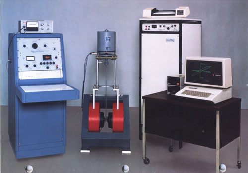
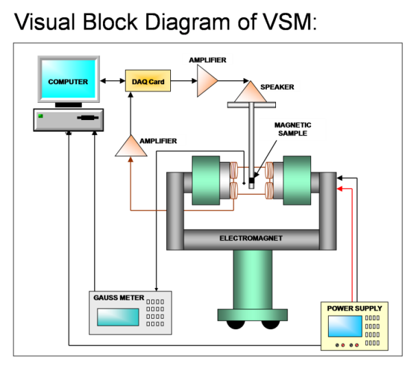
Figure 5 – Schematic of a vibrating sample magnetometer (6)
1-1-5- The electric magnet
has external dimensions of about one meter and can create a magnetic field in the area between two poles with a width of mm mm and a diameter. In order to cool the magnets, distilled water flow is used in the pipes inside the system. Its power supply produces DC current up to 2 amps and its control panel is shown in Figure (6) [8].
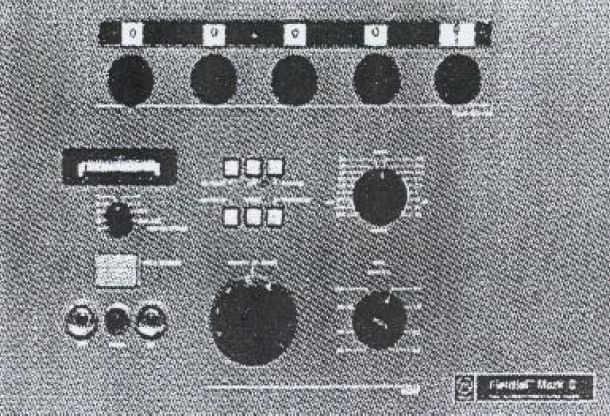
Figure 6 – Power supply [8]
2-1-5- Mechanical part
This part is designed to keep the sample in a suitable place, rotate it and produce suitable mechanical oscillations. The mechanical part is mounted on an electric magnet and consists of three parts: the oscillator generator, the sample holder, and the oscillator isolator.
Through the middle coil (the coil is simply made up of a wire coil), an AC current with a frequency of ٨٢ Hz passes to produce oscillation. The middle part of the spring plates is affected by the force of the oscillating field and oscillates, and with it, the rod of the sample and consequently the magnetic sample oscillates along the vertical. The oscillating section is connected to the moving plates of capacitors. The reaction force of the oscillations that enters the coil and the magnet causes them to oscillate. To eliminate these oscillations and prevent its transfer to the base and the formation of a static field by the main magnet, an oscillator isolator is used which, as a mechanical resonator, absorbs the energy of the oscillations caused by the reaction force. The specimen mounted at the end of a non-magnetic rod must be located exactly at the center of symmetry of the magnetometer winding system (located between the poles of the main magnet).
3-1-5- Electrical part
As mentioned before, the sample oscillates in the vertical direction. The signal induced in the windings is proportional to the sample magnetism and the oscillation profile. In order to measure the sample magnetism, the second factor must be omitted. The signal from the variable capacitor (mentioned) is obtained, which depends only on the characteristics of the mechanical oscillations (the second factor). Since the main signal is proportional to both factors, the sample’s magnetism is measured from the difference between the main signal and the capacitor-induced signal and amplified by a differential amplifier. Thus, possible changes in oscillating factors will not affect the size obtained for the sample magnetization [8].
2-5- Performance of VSM
device Magnetometers measure the magnetization of a sample of material with different dimensions in different ways and in different conditions in terms of temperature, magnetic field and sample orientation, and various diagrams that show Display the different properties of the material. Magnetometers include different magnetometer systems based on the frequency of currents passing through them, which are based on similar measurements. Some magnetometer systems include vibrating sample magnetometer (VSM), rotating sample magnetometer (RSM) and alternating force gradient magnetometer (AGFM) and [1].
The VSM device operates according to Faraday’s induction law. This law states that a change in the magnetic field creates an electric field. By measuring the induced electric field, information about the changes in the magnetic field can be obtained. First, the sample is placed in a constant magnetic field. If the sample is magnetic, a constant magnetic field magnetizes the sample by aligning the magnetic fields or magnetic spins of the atoms in the direction of the field. The larger the magnetic field, the more magnetic the sample. The magnetic moment of the sample induces a magnetic field around the sample. Now if the sample vibrates up and down, the induced magnetic field changes with time, and its changes can be observed with the induced current in a set of windings. This induced current is proportional to the magnetism in the sample. Stronger magnetization produces a larger induction current. The induced current is amplified and transmitted to a computer connected to the set for display. With the help of software, the results can be controlled and displayed. This system determines the amount and manner of magnetization of the sample as a function of the intensity of changes in the applied magnetic field. A sample that is located in a constant magnetic field and vibrates mechanically and with sinusoidal motion, by changing the magnetic flux, induces a driving force in the set of windings. The magnetic flux is obtained from the following equation:
Where A and B are geometric factors related to the set of windings, D and MS are the demagnetization coefficient and particle magnetization, respectively, and ω are the vibration frequency. Therefore, the driving force is obtained as follows:
Where C is a constant and its value can be determined by the standard nickel magnetization, the value of which is known (6).
In this system, the basis of magnetism measurement is the signal resulting from the mechanical oscillations of the sample, which is induced in a series of sensitive windings. This signal has a linear relationship with the sample magnetic moment. The samples are compared relatively. For this purpose, a calibrated standard is prepared from a magnetic moment, such as a standardized small sphere of pure nickel [8].