

Radar transmitter coil calibration method
Loll transmitter calibration method
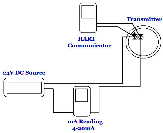
- Adjust the radar transmitter coil calibration, HART connection, power supply, and multimeter as shown below (see figure below).
- Check the configuration of the lower amplitude value (0% level, 4 mA) and the higher range value (100% level, 20 mAh). Make sure the input data matches each data sheet. For example, the low range value is 10 inches and the high range value is 35 inches (both measured from the bottom of the radar transmitter probe).
- Fill the surface transmittercompartment with water up to 0% Read the level measurement on the LCD transmitter (or in connection with HART). Set this condition to level 0 ٪ via the HART connection.
- Read the mA output of the transmitter using a multimeter. (If available) Adjust via the HART connection so that the output of the transmitter (on the multimeter) is 4 mA.
- Fill the radar transmitter coil with 100% Read the level measurement on the transmitter LCD (or in the HART connection). Set this condition to 100% via HART communication.
- Read the mA output of the transmitter using a multimeter. (If available) Adjust via the HART connection so that the output of the transmitter (on the multimeter) is 20 mA.
Calibration adjustment chart
Typical tools required
- Power supply 24 VDC
- Digital multimeter
- Connection to water supply
- HART communication
- Screwdriver set
- Wrench set
Note:
Points 1, 2 and 4 of the above common instruments can be replaced by a single multi-purpose calibration available on the market. This routine maintenance method is just a picture of how to regularly service a guided wave radar transmitter for academic purposes only. This routine should not be used as a daily work guide. The specific maintenance manual of the transmitter must be used in detail.