
Siemens Positioner Calibration Model SIPART PS
Siemens SIPART PS Positioner is a smart electronic positioner. For details on the certification method, certifications, permits, warnings and executive precautions, refer to the manual of this positioner.
Before starting the calibration, check that the positioner is properly mounted on the control valve, even if all the hardware parts are rigid. Also check that the stem coupling is not loose.
Photo No. 1
Positioner connections:
Remove the outer cover of the positioner. Pay attention to the terminal plate and make the appropriate electrical connections. Before applying the supply air pressure, find the minimum air pressure required for the actuator and adjust it by the pressure regulator. Note that applying additional supply air pressure to the positioner may result in human injury or equipment damage. Apply the appropriate supply pressure to the PZ pneumatic port. Ports y1, Y2 are the outputs of the positioner.
How to work with the positioner:
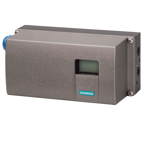
As you can see in the figure below, the Siemens PS2 positioner has an LCD indicator and three input buttons.
Photo No. 2
When we turn on the positioner for the first time, the following phrase is displayed on the screen. NOINI stands for No initiation.
Photo No. 3
Use the scroll buttons (∆ and ▽) on the positioner to move from fully closed to fully open. Observe the displacement of the valve and make sure that the valve moves freely. If you press only one of the buttons, the actuator moves slowly. To move the actuator quickly, hold down one of the scroll buttons and then press the other scroll button. If no movement occurs, reverse the order in which the buttons are pressed. When the actuator reaches its actual position, reverse the order in which the buttons are pressed so that the actuator moves quickly and reaches the opposite end position. Make sure that even the feedback joints move freely and do not get stuck throughout the range of motion. Release the scroll buttons to stop the movement.
Positioner calibration:
- Drive the actuator using the movement buttons and place it in the middle of the Stroke range.
- Rotary actuator: Make sure the Transmission Slide bar is set to 90 ° . The label on the terminals and buttons describes how to adjust this bar. The end of this yellow bar can be seen at the top or bottom of the positioner. Use a small screwdriver wrench and push the transmission bar to the opposite side of the clutch wheel and set it to 90 ° .
Akchvytvr line to Vlvhayy Stroke length is 1.25 inches maximum on Transmission Slide bar 33 0 Place. If our Stroke is larger than 1.25 inches, you must set the Transmission Slide bar to 90 ° . Refer to the label between the terminals and the buttons. The end of this yellow bar can be seen at the top or bottom of the positioner. Using a small screwdriver, push the Transmission bar toward the Clutch wheel and set it to 33 ° C.
Photo No. 4
- Press and hold the B button to enter the settings mode. The number shown in the lower left corner is the parameter number.
Photo No. 5
- Now parameter number 1 must be displayed. To change the parameter number, you can press and release the B button.
- Linear actuator: If the actuator is linear, the display screen should display the following phrase.
Photo No. 6
You can use the (∆ and ▽) buttons to edit the parameter.
Rotary actuator: Now if the actuator is rotary, the screen should display the following phrase.
Photo No. 7
Here, too, you can use the (∆ and ▽) buttons to edit the parameter.
- Linear actuator: Press the B button once to display the following phrase:
Photo No. 8
Use the (∆ and ▽) buttons to select a phrase that matches the settings in step 2.
Rotary actuator: Press the B button once to display the following phrase:
Photo No. 9
Use the (∆ and ▽) buttons to select a phrase that matches the settings in step 2.
- Press the B button (once for rotary actuator and twice for linear actuator) to display the following phrase:
Photo No. 10
- Hold down the ک button until the actuator starts moving, then release it.
- If the actuator stops after starting and the display shows the following phrase, it means that the tolerance is above the allowable level.
Photo No. 11
Step A Make sure the Transmission Slide bar is set correctly. If set correctly, perform step B.
(Step B) Adjust the Clutch Wheel feedback.
Clutch Wheel feedback should be easy to rotate with finger pressure. Otherwise, using a small screwdriver, turn the yellow wheel to the left until the Clutch Wheel is released and rotates easily.
So if you encounter the above phrase during the positioning calibration, turn the Clutch Wheel so that the number 0 appears instead of u. In this case, a number is displayed in the upper right corner of the screen should be 6.0.
Photo No. 12
(Step c) Linear actuator: Press the. Button.
Rotary actuator: Press the. Button.
- RUN3 will show the actuator opening and closing speed.
Optional: To test for leakage, hold down the. Button for 2 seconds until the display shows the following phrase.
Photo No. 13
The leak test lasts 60 seconds, after which the leak rate is displayed as a percentage of the stroke leak per minute.
Photo No. 14
- To continue the calibration, press the ک button until the RUN4 and RUN5 steps are completed.
- After RUN5 the calibration is completed and the phrase FINISH is displayed on the screen.
- Press the B button once to return to the positioner mode.
Photo No. 15
- Now the positioner is calibrated for the valve and actuator and you have to decide whether to go out of settings and return to automatic mode or adjust other parameters.
- To return to automatic mode, hold down the B button to display the following statement.
Photo No. 16
After exiting the mode, the positioner settings automatically enter manual mode, which can be moved from the △ and ▽ buttons.
Photo No. 17
- Press and release the B button once to enter automatic mode. In this mode, the positioner receives the input signal from the controller and strokes the valve accordingly.
Photo No. 18