

Types of temperature resistance sensors or RTD are available
| Rueger temperature resistance sensor | Endress & Hauser temperature resistance sensor |
| Emerson Temperature Resistance Sensor | Delta Fluid temperature resistance sensor |
| Euromisure temperature resistance sensor | |
| Fuji temperature resistance sensor | Nagano Temperature Resistance Sensor |
| Pyro Controle temperature resistance sensor | Atbin temperature resistance sensor |
| Thermo Electric temperature resistance sensor | Wise Control Temperature Resistance Sensor |
| Nilgata temperature resistance sensor |
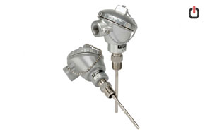
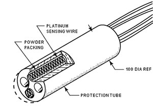
RTD sensors are made of special metals such as platinum, nickel or copper, and their electrical resistance changes linearly with temperature fluctuations. The electrical resistance generally increases with increasing temperature, in which case the equipment has a positive temperature coefficient. The temperature coefficient determines the sensitivity of the RTD. Because RTD sensors are fragile, they are housed inside a protective shell.
RTDs are very accurate compared to thermocouples and are gradually replacing thermocouples to measure temperatures below 600 ° C. It is worth noting that in analog circuits, RTDs are mostly used as temperature sensors.
RTD sensors based on manufacturing method
RTD sensors are divided into two types, winding and thin film, depending on how they are made, which we will describe below:
Wrapped RTD sensor
Most RTD elements consist of a finely wound coil around a ceramic or glass core. This element is usually very brittle, so it is often placed inside a sheath probe to protect against short circuits and create vibration resistance. Coiled RTDs are stable but have a slow thermal response due to the low electrical conductivity between the Pt and the measured point. These types of sensors are suitable for working in any environment and any type of application.
Thin film RTD sensor
In the RTD sensor, a thin layer of platinum film is placed on a ceramic layer in the form of resistance, and then the film is covered with glass or epoxy to resist moisture and vibration. Thin film RTDs have a fast thermal response, low sensitivity to vibration and the ability to create higher resistance for a given size. These RTDs are less stable than coiled RTDs, but because of their much lower price, they are widely used.
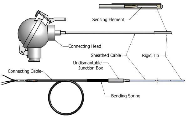
RTD components
The components of resistor sensors include resistor element, process connection, wiring, cold end, RTD tube and outer diameter, each of which is described below:
Platinum resistance element
The main part of temperature measurement is the resistance element, which can be made of platinum, nickel and copper. The length of the resistance element varies from 2 to 3 inches. The standard alpha coefficient is 0.00385 and the standard resistance is 100 ohms at 0 ° C.
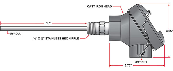
Process connection
Process connection in RTDs, like thermocouples, includes all standard connections such as compression, welding, spring and so on.
Wiring
RTDs are made in two, three and four wires. Four-wire RTDs are used to accurately measure temperature in special cases and have two wires to transmit sensor current and two wires to measure voltage on the sensor element. Insulation of sensors and wires is selected according to the type of application, the insulation of wires is often Teflon and fiberglass.
Cold end
Cold connection in RTDs can be in the form of two branches, bare wire, terminal and other connections related to the thermocouple.
RTD tube
Depending on the type of application, pipes of different materials are used. For example, for use below 500 degrees Fahrenheit, 316 stainless steel is used, and for use above 500 degrees Fahrenheit, Inconel 600 is used.
External diameter
The outer diameter of the RTD is 0.063 to 500 inches.
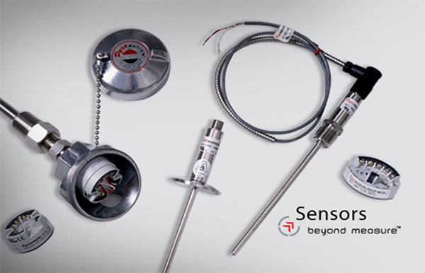
RTD images
(Sensors, shells and other components)
Types of RTD sensors
RTDs are classified based on the type of metal used in their sensors.
-
RTD with platinum sensor
Platinum element RTDs are the most common type of RTD used in the process industry. Platinum is the most common metal for RTDs, including the following properties of platinum
- Chemically neutral
- Good calibrated accuracy
- Stable and repeatable
- Creating a relationship between temperature changes and resistance,
- High temperature coefficient
The two main types of platinum RTDs are known as PT100 and PT1000, but other sensors such as PT50, PT500 and other platinum families are also available, depending on the type of user and typically PT100 sensors. They are mostly used in manufacturing industries. It is worth noting that increasing the cable length in PT1000 sensors with two wires causes less error than PT100 sensors.
RTDs with platinum sensors are available in PT100, PT500 and PT1000, the most important of which is PT100. The table below shows the temperature coefficient and sensitivity of various platinum sensors.
| Resistance at 0 ° C | allergy |
| 100 ohms | 0.385 |
| 500 ohms | 1,925 |
| 1000 ohms | 3.85 |
* All values of temperature coefficient of resistance in the above table are equal to 0.00385 ohms per degree Celsius.
Temperature sensor PT100
The expression PT states that the material of the metal is platinum and the expression 100 is the resistance of the metal in ohms at 0 ° C. Also, these sensors have a resistance of 134 ohms at a temperature of 100 ° C.
PT100 sensors measure the temperature range of -200 to 600 ° C, and with increasing or decreasing each degree Celsius, their resistance decreases or increases by 0.385 ohms . Therefore, even a small error in measuring the resistance, for example, the resistance of the wires leading to the sensor, can cause a large error in measuring the temperature. Unlike thermocouples, the PT100 does not require special cables to connect.
The PT100 is also relatively resistant to electrical noise and is therefore suitable for measuring temperature in industrial environments, especially around motors, generators and other high-voltage equipment. It is worth noting that this model has achieved many standards. Which is named below:
- Standard PT100 sensors
- European standard (DIN or IEC60751)
- American Standard (JIS)
- In European standard or IEC751 for short, electrical resistance at a temperature of 0 ° C is considered 100 ohms and the temperature resistance coefficient is 0.00385 (at a temperature between 0 to 100 ° C).
Many factors affect the choice of PT100 sensor, some of which include the following:
- Temperature range
- Probe and cable suitable for use
- Type of fluid and metals (corrosive or conductive)
- Soldered joints on the thermocouple cable should not be used at temperatures above 170 ° C.
Temperature sensor PT500
In these sensors, the sensor is made of platinum and has a resistance of 500 ohms at a temperature of 0 ° C.
Temperature sensor PT1000
In this case, too, PT stands for platinum for the metal, and the resistance is 1000 ohms at 0 ° C.
-
RTD with Copper sensor
Copper RTD elements are very linear in their temperature range, but have limited accuracy and their temperature range is smaller than that of platinum elements. RTD sensors are made of low-cost copper, but it should be noted that copper oxidizes at very high temperatures. The temperature range of the copper sensor is -200 to 260 degrees Celsius. Copper elements are often used to measure temperature in engine windings and bearings, although accuracy is not critical.
-
RTD with Nickel sensor
Nickel RTD elements have a higher temperature coefficient than platinum and copper RTD elements and have good corrosion resistance, but poor linearity, limited accuracy, lower repeatability and a relatively small operating temperature range of -80 to 260 ° C. Have. Nickel RTDs are less expensive than platinum, and their elements are commonly used in applications where accuracy is not an issue.
| Sensor material | Temperature range (degrees Celsius) | Property | The best amount of resistance | Temperature coefficient of resistance |
| Platinum | 260- to 850 | Good linear stability Excellent |
100 ohms at 0 ° C | 0.00385 |
| Copper | 100- 260 | Good linearity | 10 ohms at 25 ° C | 0.00427 |
| نیکل | 100- 260 | Low cost, high sensitivity |
120 ohms at 0 ° C | 0.00672 |
Types of RTD
Based on the method of measuring the electrical resistance of their sensors
- Tow-Wire RTDs
- Three-Wire RTDs
- Four-Wire RTDs
To accurately read the temperature of an RTD, the resistance of the RTD sensor element must be measured. Each copper interface wire that connects to the RTD sensor element has its own resistor, which is added to the resistance of the RTD sensor element. If the added resistance is ignored, an error will occur and the temperature measurement will not be accurate. The resulting error is called the “interface wire effect”. The longer the wire, the greater the error.
To compensate for the effect of the interface wire, three-wire and four-wire RTDs are used instead of two wires. Three-wire RTDs are created by connecting an extra wire to one of the primary wires, and four-wire RTDs are created by connecting an extra copper wire to each of the existing interface wires.
Tow-Wire RTD sensor
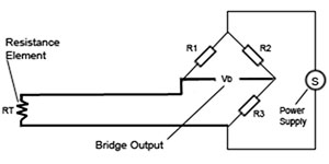
This model is the most common and simplest type of connection in RTDs and is used when low measurement accuracy is used.
The main problem in measuring two wires is that the change in resistance due to the interface wires is not known and the measuring equipment can not differentiate between the RTD resistance and the resistance of the interface wires. The resistance of the two interface wires adds to the resistance of the RTD element and reduces the measurement accuracy. Two-wire RTDs are commonly used in HVAC applications.
In this method, a maximum of 100 meters of cable can be used.
Three -Wire RTD sensor
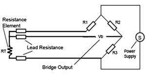
Three-wire RTDs are able to compensate for the impact of interface wires, but incur the additional cost of being three-wire. There are several ways to compensate and find the resistance of the RTD element. One common method is to use Ohm’s law.
If we are the same sex and length, we have three wires
R1 = R2 = R3
By measuring the resistance of paths 2 and 3 (R2 and R3), only the resistance of the copper wires is obtained, and since all the resistance of the copper wires is equal, the value (R2 R3) is subtracted from the total resistance of the path R1 R2. And the value of RT resistance is calculated.
RT = (R1 + 2 + RE) – (R2 + 3)
Three-wire RTD is commonly used in industrial applications to eliminate the average resistance of wires. When the distance between the sensor and the measuring or control device is long, using a three-wire model instead of four wires can save costs. In this method, a maximum of 600 meters of cable can be used.
Four-Wire RTD Sensor
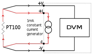
Four-wire RTDs have the best compensation because they are able to fully compensate the strength of the wires regardless of the length of each wire and be used in sensitive services that require high accuracy. In this method, 4 sensing points eliminate the voltage drop across the measurement that leads to an error to increase the accuracy of the measurement. Each thermoelectric voltage eliminates leaks generated by different wires or screw connections by reversing the 1 mA current direction and connecting to a digital voltmeter (DVM). Thermoelectric voltages are generated in one direction only.
Convert temperature resistance
Once the RTD resistance has been determined, it must be converted to its corresponding temperature value. In transmitters, one of the following two methods is used:
Based on RTD standard
- In IEC-751 standard
In IEC-751, the maximum value of “sensor interchangeability error” is defined at a given process temperature in two classes, A and B. These classes are used to specify platinum RTDs.
- RTD Class A
In Class A, the accuracy of RTDs is defined as 15 0.15 ͦC + (0.002T) ͦC, where T is the process temperature in ͦC. Class A RTDs are more expensive than Class B RTDs.
- RTD Class B
In Class B, the accuracy of RTDs is defined as ± 0.3 + C + (0.005T) ͦC, where T is the process temperature in ͦ C. Because Class B RTDs are cheaper than Class A RTDs, they are more widely used in industry.
| Sensitivity class | allergy | Thin film structure (degrees Celsius) | Coiled structure (sensitivity class) |
| A | ± (0.15 + 0.002 | t |) | 100- to 450 | 30- to 300 |
| B | ± (0.3 + 0.005 | t |) | 196- to 600 | 50- to 500 |
Callendar-Van Dusen equation
The amount of resistance change due to temperature change is calculated as follows.
R0 (1 + α_1T + α_2T2 +… + α_nTn +…)
RTD sensor accuracy
Accuracy is a combination of base resistance tolerance or resistance tolerance at calibration temperature and temperature coefficient of resistance tolerance or tolerance at characteristic slope. In fact, when we talk about accuracy, we usually mean the degree of deviation, the temperature, or the degree of tolerance of that sensor. There are several standards for expressing the accuracy and tolerability of platinum RTDs, the most common of which is IEC 751 1995 and has two performance classes A and B.
| Platinum | PT100 | PT500 | PT1000 |
| Temperature (degrees Celsius) | Resistance (ohm) | ||
| 50- | 80.3 | 401.5 | 803 |
| 40- | 84.3 | 421.4 | 843 |
| 30- | 88.2 | 441.1 | 882 |
| 20- | 92.2 | 460.8 | 922 |
| 10- | 96.1 | 480.4 | 961 |
| 0 | 100 | 500 | 1000 |
| 10 | 103.9 | 519.5 | 1039 |
| 20 | 107.8 | 539 | 1078 |
| 25 | 109.7 | 548.7 | 1097 |
| 30 | 111.7 | 558. 4 | 1117 |
| 40 | 115.5 | 577.7 | 1155 |
| 50 | 119.4 | 597 | 1194 |
| 60 | 123.2 | 616.2 | 1232 |
| 70 | 127.1 | 635.4 | 1271 |
| 80 | 130.9 | 654.5 | 1309 |
| 90 | 134.7 | 673.5 | 1347 |
| 100 | 138.5 | 692.5 | 1385 |
| 110 | 142.3 | 711.5 | 1423 |
| 120 | 146.1 | 730.3 | 1461 |
| 130 | 149.8 | 749.2 | 1498 |
| 140 | 153.6 | 767.9 | 1536 |
| 150 | 157.3 | 786.6 | 1573 |
| 160 | 161.1 | 805.3 | 1611 |
| 170 | 164.8 | 823.9 | 1648 |
| 180 | 168.5 | 842.4 | 1685 |
| 190 | 172.2 | 860 | 1722 |
| 200 | 175.9 | 879.3 | 1759 |
* The standard value in the table above is IEC751.
* In the table above, the values for class A / B are stated.
| Temperature tolerance (degrees Celsius) | |
| Class A | Class B |
| 0.05 | 0.05 |
| 0.07 | 0.1 |
| 0.09 | 0.15 |
| 0.11 | 0.2 |
| 0.13 | 0.25 |
| 0.15 | 0.3 |
| 0.17 | 0.35 |
| 0.19 | 0.4 |
| 0.2 | 0.43 |
| 0.21 | 0.45 |
| 0.23 | 0.5 |
| 0.25 | 0. 55 |
| 0.27 | 0.6 |
| 0.29 | 0.65 |
| 0.31 | 0.7 |
| 0.33 | 0.75 |
| 0.35 | 0.8 |
| 0.37 | 0.85 |
| 0.39 | 0.9 |
| 0.41 | 0.95 |
| 0.43 | 1 |
| 0.45 | 1.05 |
| 0.47 | 1.1 |
| 0.49 | 1.15 |
| 0.51 | 1.2 |
| 0.53 | 1.25 |
| 0.55 | 1.3 |
Diagram of resistance changes in temperature in RTD sensors
As shown in the figure below, the higher or lower the operating temperature of the sensors, the lower the sensor accuracy.
Standard accuracy chart on RTD sensor
RTD application
- Oil and gas industry
- Water and wastewater industry
- Power plants
- Air conditioners and cooling systems
- Chemical and petrochemical industries
Advantages of RTD temperature resistance sensor
Advantages of using RTDs compared to thermocouples
- They have better accuracy and reproducibility.
- RTD signals are less sensitive to noise and have a higher signal-to-noise ratio.
- They are more linear in the operating temperature range.
- Cold connection errors are not present in RTDs.
- RTD (Drift) deviation is predictable while in thermocouple it is not predictable.
- Changes that occur over time due to mechanical shocks, corrosion, and temperature cycles affect the output of an RTD or thermocouple. These changes can be removed with some consideration for RTDs. This feature is not available for thermocouples.
- RTDs do not require special extension cords.
Tips on RTD
- They are fragile and have large dimensions.
- Due to their larger dimensions than thermocouples, they have a slower time response to temperature changes. Their response time is usually from 0.5 seconds to 5 seconds. Response time increases with increasing RTD dimensions. Using a thermowell can double the response time.
- They have problems with overheating. For this reason, they are applicable for temperatures below 600 ͦ ° C.
- They are sensitive to electrical noise.
- The cost of testing and diagnosing their defects is high.
- They have a higher price compared to thermocouples.