

What is a thickness gauge?
Thickness gauge is a tool for performing basic non-destructive tests, which is used to measure thickness when we have access to the surface of the object. These thickness gauges can be divided into the following types in terms of manufacturing technology.
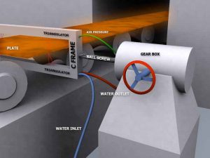
1- Laser thickness gauges These thickness gauges are devices that are placed in the form of C Frame on the piece or around the plate and measure the thickness of the plate (plate), tube or ingot with the help of laser beams. This device can measure the thickness of one or more points of the page or part online and on the production line in one channel and two or more channels and display it on the screen.

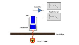
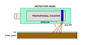
2- Beam thickness gauge is a tool that is widely used in automotive, steel, machine, petrochemical, cement and pipeline industries and even nuclear technology, including non-destructive testing and analysis of composition and structure. The material pointed out. This equipment is used to measure the thickness of sheet products such as paper, steel, aluminum, rubber, plastic, coatings and plating, which is designed and manufactured based on the transmittance and scattering of the beams.
3- Magnetic thickness gauges, which are mainly known as paint and coating thickness gauges or car paint thickness gauges , have a major application in measuring coatings on surfaces in liquid or powder form. In addition, on the underlying surfaces, painted iron (substrates) of iron and steel, which are chrome-plated, cadmium and phosphated, are also used.
4- Vortex flow thickness gauge has more general applications for thickness gauges of coatings, which include liquid and powder coating on aluminum and non-magnetic stainless steel as well as on anodized aluminum.
Many thickness gauges today work on the basis of a combination of both magnetic induction and eddy current mechanisms. This allows the consumer to measure in a wider range without changing the type of thickness gauge. The consumer can usually choose between the original thickness gauges, which only show the thickness value digitally, or the more advanced digital thickness gauges, which store the measured values, and give us statistical information such as average data, standard deviation. Or offers the highest and lowest values of the selection to choose one.
Another type of selection is based on the shape of the piece being measured. One type of thickness gauge and probe cannot be used for all the parts being measured. When faced with a piece with complex shapes. The user must use different and separate probes that are offered in the Cyanco store.
For example, in a thickness gauge, measuring the thickness of the inner diameter of a pipe may require a 90 degree probe, while measuring thickness on a flat surface requires a zero degree probe for easier access to the measured surface. has it.
5- Ultrasonic thickness gauge Ultrasonic thickness gauge , which is known as metal thickness gauge or tube thickness gauge .
Ultrasonic thickness gauges are used to measure the thickness of metals, ceramics, composites, plastics, and so on. One of the most important and prominent features of ultrasonic thickness gauges is the ability to measure the thickness of the coating without removing the coating, this feature has made ultrasonic thickness gauges widely used in shipbuilding and pipelines. In the past, calipers had to be used to measure the thickness of objects such as pipes, which caused the sample to be cut to fit the edges of the caliper. This operation caused a lot of losses, especially in higher dimensions. On the other hand, ultrasonic thickness gauges are able to measure the thickness in the production line and after the sample solidifies only by wetting the product surface. Today, with the use of ultrasonic waves, the thickness of objects can be easily measured at any desired point without cutting.
How ultrasonic thickness gauges work
The method of working with ultrasonic thickness gauge is to measure the thicknessBy this device, sound waves are emitted by the probe and after passing through the thickness of the sample, it enters the air environment inside the sample. Air acts as an insulator and determines the speed at which waves pass through the body of the sample, taking into account its time, using the formula for the thickness of the part. For this reason, a thin layer of water should be placed on the surface of the piece to allow the conduction of waves. The basis of all ultrasonic thickness gauges is based on measuring the time interval between the passage of sound frequency pulses through the test material. The frequency or step of these sound pulses is beyond human hearing (generally one to twenty million cycles per second, as opposed to the human ear, which is about twenty thousand). These high frequency waves are generated and received by a device called an ultrasonic transducer; The converter converts electrical energy into mechanical vibrations and vice versa.
The ultrasonic waves used in industrial experiments cannot pass well through the air, so a pair of interfaces such as propylene glycol, glycerin, water or oil are used, often between the converter and the part. These devices typically use the “impact-reflection” method for measurement. The sound waves generated by the transducer enter the part and are reflected from the other part and return to the transducer. The device accurately measures the time interval between the initial reference pulse by reflecting it. Typically this interval is only one millionth of a second. If the thickness gauge is programmed with the speed of sound in that sample, the thickness can be calculated by simple mathematical relations from this time interval.
t = VT / 2
t = piece thickness V = sound velocity in that material T = round trip time measured
The important point is that the speed of sound in the test material is an essential part of this calculation. In different materials, the speed of sound transmission is also different and the speed of sound will change significantly with temperature. Therefore, it is necessary to calibrate the ultrasonic instrument according to the speed of sound in the test material and the accuracy of the measurement depends on this calibration.
Ultrasonic thickness gauges can be adjusted to measure metals, plastics, ceramics, composites, epoxies and glass. Biological and liquid samples can also be measured by this method. Materials that are not suitable include wood, paper, concrete and foam, which are not thickened in this way.
With this method, it is possible to measure extruded plastics or rolled metals online or simultaneously, as well as measure layers or coatings in multilayer materials.
What are the components of an ultrasonic thickness gauge?
Ultrasonic thickness gauges mainly consist of a circuit equipped with transmitter and receiver sensors, a controller and a logic timer, which is mainly a microcontroller or microprocessor, a display and a power supply. A sensor controlled by a microcontroller sends a PWM pulse to the actuator. Ultrasonic pulse is generated by a transmitter transducer connected to the test sample. The reflections are received from the end or inside the surface of the sample by the receiver and converted into electrical signals and given to an amplifier (operational amplifier) to analyze the data. And select the appropriate reflective signals to measure the time interval. When returning, the reflections received by the timing function, the reciprocating time interval of the sound pulse in the test sample are accurately measured.
The microprocessor then uses this interval along with the speed of sound and data stored in the device memory to measure thickness. This thickness is then displayed on the screen and updated periodically. The read thickness may also be stored in external memory or transferred to the printer, depending on the capabilities of the thickness gauge device.
Types of ultrasonic thickness gauges
Most ultrasonic thickness gauges are of the following four types:
1. Converter – Contact
2. Delay Line
3. Floating
4. Two- component
Contact converter:
Thickness gauges that use direct contact converters are generally simple to implement and are widely used in industrial measurements. The time intervals are the initial induction pulses up to the first reflection minus the time factors of the coupled layer as well as the electrical delay in the measuring instrument and the correction factors that take into account the thickness of the converter instrument surface. Contact transducers are commonly used in direct contact with the test part.
Delay line converter:
Delay line converters are made of a plastic, epoxy or silica welded cylinder and are known as the delay line between the sensor of the converter and the workpiece. Thin material is measured. This layer can act as a surge arrester and can also send waves to a piece that is very hot to be measured by contact heat exchangers that are sensitive to heat. The delay line can be shaped so that it can be easily coupled with curved surfaces and limited spaces. Timing of reflections in delay line applications may be one of two modes: the end of the delay line to the beginning of the back wall reflection or between successful wall reflections.
Timing between successful wall reflections improves the measurement accuracy of thin materials and increases the measurement accuracy more than the contact method for special applications such as hot objects.
Floating
converter:
Floating converters use a column of water to transfer sound energy into the part. They can be used to measure moving products online, to scan or rotate measurements, or to optimize sharp radii and grooves, and their timing is similar to that of linear latency.
Two-component converter:
Two-component converters are primarily used to measure rough surfaces. They are separate transmitter and receiver converters, both mounted on a delay line at a variable angle to focus the energy of a selected distance below the surface of the part. Also, the accuracy of this type of thickness gauges is less than other types. They are designed for rough applications only.