

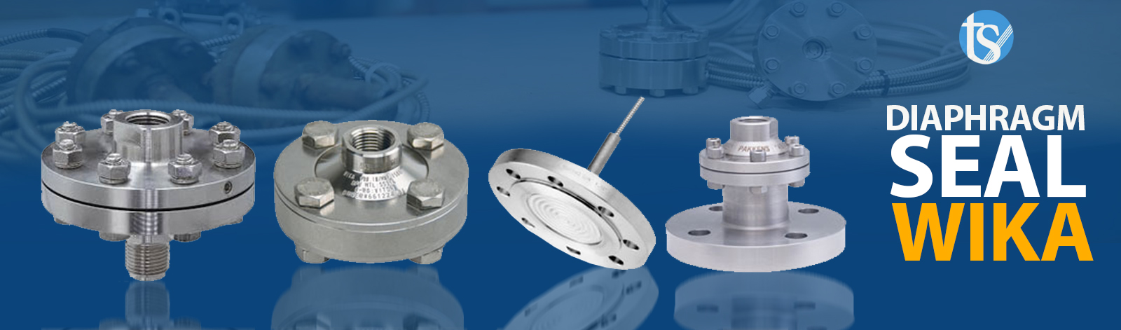
Equipping the industry supplying and equipping the oil, gas and petrochemical industries, selling all kinds of Vika diaphragms
- Vika diaphragm for manometer
- Vika diaphragm for pressure gauge
- Vika diaphragm for transmitter
- Vika diaphragm for manostat
Flood diaphragm
Seal diaphragms, also called chemical seals, are used to separate pressure gauges, switches, and transmitters from clogging and corrosive environments. The diaphragm body of standard seals and diaphragms is made of stainless steel, in addition to a variety of materials from carbon steel to hostel suede alloy are available to meet the demands of most applications. Vika flood diaphragms can operate in pressure applications from H 2 O 10 to 15000 psi and ambient temperatures between -130 and 2 752.
Examples of typical flood diaphragm applications
- The environment is corrosive and may damage a sensitive element such as a Bourdon tube gauge, pressure switch or transmitter diaphragm.
- The ambient temperature may be too high for a standard gauge, switch or transmitter to malfunction.
- The medium is very viscous or tends to crystallize, polymerize, and may block the pressure port of a gauge, switch, or transmitter.
- The environment is inhomogeneous or contains suspended solids that may clog the pressure port of the gauge, switch, or transmitter.
- Remote reading required. A flood diaphragm with a capillary line allows the installation of a remote pressure device.
- The environment is toxic and dangerous and may contaminate the environment. A well-designed slab diaphragm provides more protection, for example all-welded designs.
- Applications that require high compression protection.
Vika flood diaphragm systems are excellent and save consumption by:
- Extend the service life of pressure tools
- Reduce installation costs
- Reduce or eliminate maintenance costs
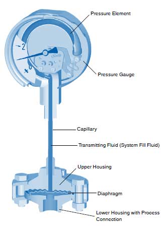
Principles of operation
The following figure shows the operating principles of a flood diaphragm set. A pressure gauge such as a conventional pressure gauge or electronic pressure transmitter is mounted directly to the seal diaphragm or connected to the seal by a capillary or cooling element. The diaphragm inside the diaphragm separates the flood, gauge or transmitter from the process environment. Each part of the flood diaphragm (ie diaphragm, bottom sheath, gaskets) that is exposed to the process environment is selected from materials that are resistant to temperature, pressure, and possible chemical attack by the process environment. The seal diaphragm is also filled with a transfer fluid or system filler fluid. Any pressure applied by the process medium to the seal diaphragm is hydraulically transferred to the pressure element of the gauge / switch / transmitter and thus the pressure must be read.
Selection guide
The following details should be considered when selecting a flood aperture assembly to ensure safety and satisfactory performance. For special technical assistance regarding temperature effects, volumetric compatibility,… contact Wika or send the complete flood diaphragm specification sheet for factory analysis.
1. Process combination
Since the diaphragm and the lower chamber of the flood diaphragm are exposed to the process environment, it is essential to select a material for these components that is compatible with this environment. There are tables to help select these materials, however the customer is the ultimate source for determining the appropriate materials. Vika can not guarantee the suitability. For information on this, see the various reference guides, including corrosion tables, in reference books.
2. Temperature
Each flood diaphragm measuring system (flood diaphragm, pressure instrument, and cooling or capillary element) is filled with some filler fluid at an ambient temperature of about 70 ° C. This temperature is recorded as the system temperature. The filler fluid expands or contracts according to temperature changes. This in turn increases or decreases the pressure of the sensor element. This adds the effect of zero changes to the tool output. To reduce this effect, process and ambient temperatures must be specified when selecting a flood diaphragm system. Special advanced calibration techniques can be used to ensure the best possible accuracy. At temperatures above 300 a cooling element or capillary is recommended to protect the pressure tool.
3. Pressure range
The displacement volume on the flood diaphragm required to move the flood diaphragm measuring system (flood diaphragm, pressure instrument and capillary) must be larger than the displacement volume required to move the pressure sensor element. Typically in the lower pressure range, a larger aperture is required to run the system. Conversely, smaller diaphragms are sufficient for higher pressure ranges. Pressure transmitters also follow the general rule that at lower pressures, larger diaphragms are required.
4. Pressure tool
As mentioned above (item 3, pressure range) the flood diaphragm must have sufficient displacement capacity to activate the pressure tool to reach full scale. As a general rule, smaller gauges are more suitable for low pressure applications because less displacement volume is required for part of the flood diaphragm to excite the pressure tool.
5. Connection process
The connection process is determined by the customer. Most process connections are threaded, flanged or clamped. Additional connections are also available.
6. System filler fluid
Vika offers a wide range of system filler fluids with temperatures from -130 to 752. The chemical compatibility of the system filler fluid with the process fluid must be carefully considered in the event of a leak. In food processing applications, a non-toxic fluid must be selected. For oxidizing environments, special filler fluids are available, including oxygen and chlorine.
7. Installation position
The installation location is important for flood diaphragm systems that include capillaries. The surface difference between the flood diaphragm and the pressure tool causes hydrostatic pressure on the sensor element.
- For gauges mounted above the level of the flood diaphragm, the hand on the gauge is below the zero point.
- For gauges installed below the level of the flood diaphragm, the hand on the gauge is above the zero point.
8. Response time
Response time is the time it takes for the pressure tool to show 90% of the amount of sudden pressure change, which is especially important for seal tool sets / diaphragms that contain capillaries. Response time is significantly increased in systems with long capillaries. In applications requiring long capillaries, the response time can be reduced by using larger diameter capillary tubes and reducing the viscosity of the system filler fluid. It is recommended that increasing the inner diameter of the capillary increases the effect of temperature on the measurement system. Consult the factory if more detailed information is required.
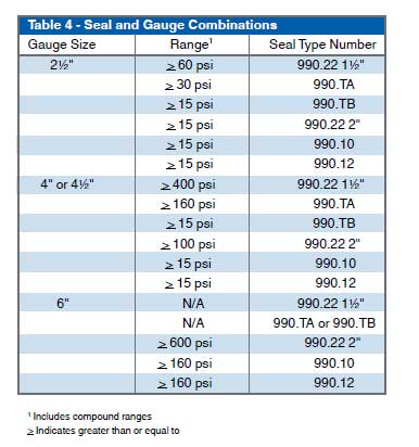
9. Matching flood and confusion
For lower ranges, the gauge priority is to access the 2XX.54 or 2XX.34 calibration settings . The table below shows the correspondence between the types of gauges and flood apertures recommended by the factory.