
multimeter
Equipping the industry representing sales of digital multimeters, pliers, analog from top European and Japanese, Chinese brands
What is a multimeter?
A multimeter is a measuring device that has the ability to measure electrical quantities of voltage, current and ohmic resistance.
Some multimeters can also measure alternating signal frequency and capacitor capacitance, and they can also detect diode and transistor pins and determine if they are healthy or defective.
Circuit connections can also be tested with a multimeter.
The multimeter is also called the AVOmeter. AVO is derived from the initials of the words Volt, Ampere, and Ohm because multimeters can measure these three quantities.
To measure the ohmic value of the resistance by the multimeter, after selecting the range related to the resistance, the wires of the multimeter should be connected to both ends of the resistor and the value measured by the multimeter should be read.
Of course, if the desired resistance is in the circuit, it should be noted that this resistance is not parallel to other elements, because then the amount of resistance is not obtained correctly.
Classification of multimeters
Analog multimeter
In appearance, an analog or hand-held multimeter usually consists of a screen with a number of calibrated lines, a hand that can move on calibrated lines, a selector, a number of terminals, a zero-setting potentiometer, and two interface wires. (Here, no attention is paid to the internal structure of the hand multimeter, and the purpose is only to get acquainted with this type of multimeter.)
Pay attention to the figure on the top right.
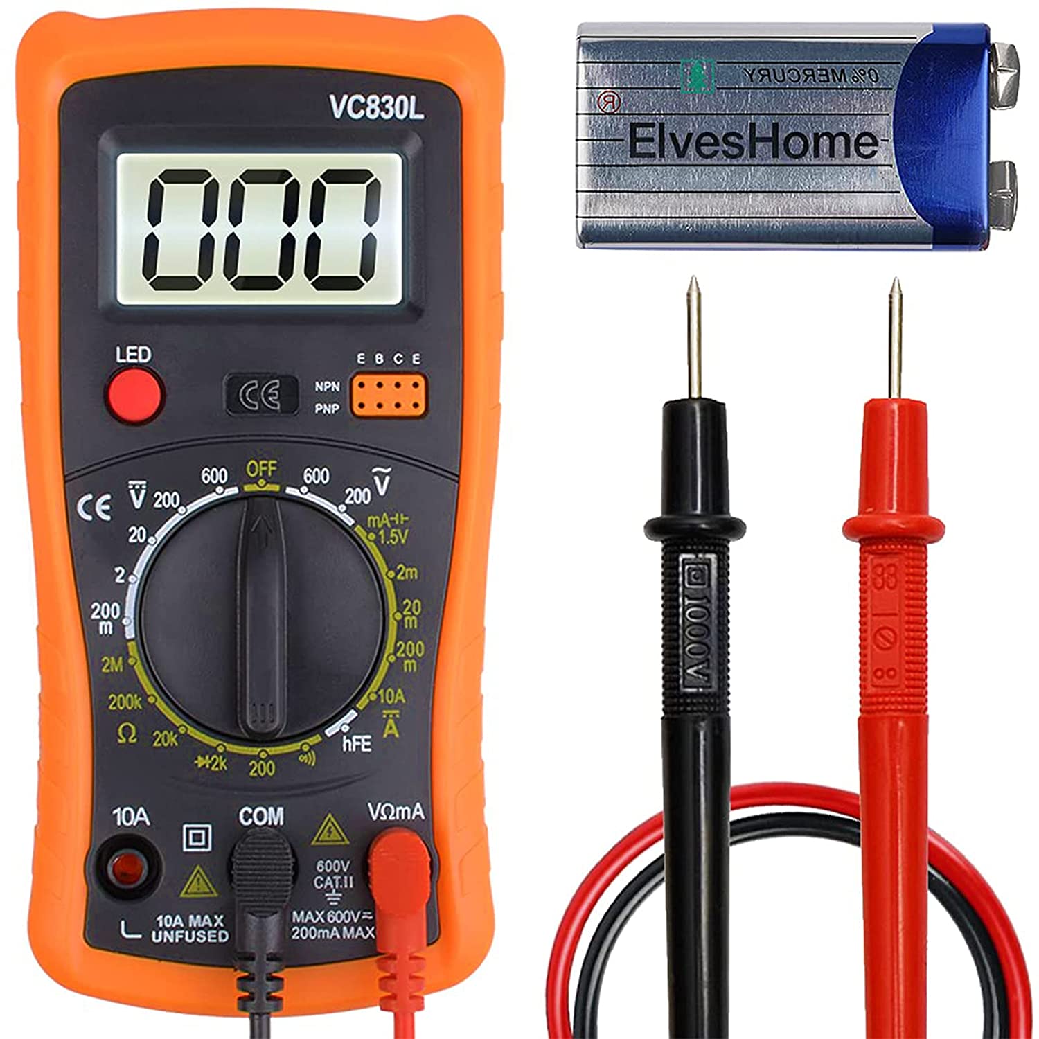
Digital multimeter
A digital multimeter displays the measured quantities in the form of digits or digits on the screen and usually also displays the unit of the measured quantity in an appropriate way.
Desktop multimeter
This type of multimeter is also digital and has more accuracy and is mostly used in laboratories.
Pliers multimeter
There is another type of digital multimeter in which, in addition to the features mentioned, there is also a rake.
With this rake, the current passing through that element can be measured without the need to series the multimeter with the desired element in the circuit.
If we place the current-carrying wire connected to the desired element between the claws of this multimeter, the multimeter displays the amount of current passing through the wire and consequently the amount of current passing through the desired element.
Therefore, with this multimeter, the amount of current can be measured easily and very quickly.
The figure shows a pliers digital multimeter.
How to use and work with multimeters
The device multimeter contains several electrical meters that can measure components such as voltage, current and resistance.
To work with multimeters, all you have to do is rotate the movable switch on the device as you wish. There is a small arrow on the rotary switch that shows the multimeter mode, this arrow is in front of any expression of the multimeter.
for example
To measure the DC voltage, place the
switch on the Vdc mode and connect the wires to both ends of the desired point.
To measure the electric current, place the
switch on the A mode and place the multimeter wire in series with the circuit.
To measure the electrical resistance, place the
switch on the ohm mode and connect two multimeter wires to the resistor.
How to measure resistance with a multimeter: (digital)
To measure resistance, do the same as measuring voltage, except that separate the resistor under test from each power supply and then test.
How to measure resistance with a multimeter: (hand)
It should be noted that there is an indicator on the selector handle that determines the scope of work in your measurements.
This device, like any other system, has two terminals, anode and cathode.
To use the device correctly, you must connect the black wire to the com negative terminal and the red wire to the positive terminal.
Now hit the power button on the device and you can start any kind of measurement.
R * 10 means that if the hand of any number indicates that number, it must be multiplied by 10 so that we can read the original value of the resistance.
For example, if our resistance is 10 kilo ohms, the hand stands on one kilo ohm, and if we multiply one kilo by 10, we get the original value of the resistance, which is 10 kilo ohms.
Range can not be read more than 50 kOhm in this row.
So if our resistance is greater than this value, we must set the selector to R * 100 and as before, whatever the hand showed, we must multiply by 100 this time.
Note that every time we set the key to R * 1 or R * 10 or باید, the zero setting must be reset.
DC voltage measurement 🙁 digital)
To measure the voltage, place the multimeter in parallel (Figure below) in the circuit and place the multimeter selector on V (AC or DC). You will then see the measured value:
DC voltage measurement: (clockwise)
We start with DC.V direct voltage.
As you can see, this section has six measurement bases that can measure from 0.25 volts to 1000 volts DC.
The way this part works is almost the same as ohm, which means that if we set the selector to 10 volts, our device can show up to 10 volts. .
DC power has + and – poles and we have to hit the black plug negatively and the red plug positively, otherwise the hand will move in the opposite direction.
You can see this classification of numbers on the page of the section where there are three categories of numbers.
The left side of the circuit is also marked with DC.V and mA.
Now if you want to test a battery or direct current power supply, you must connect the positive wire of the device to the positive power supply and the negative wire of the device to the negative power supply.
If your battery is, for example, six volts, you should set the selector to 10.
In this case, the hand shows the number 6, but if your battery is more than 10 volts and less than 50 volts, the selector should be set to 50 and if it was more, to 1000 volts.
AC voltage measurement: (clockwise)
To measure the AC voltage (such as mains electricity), the selector switch (selector) must be placed in the AC-V section.
If we set the switch to 10 degrees, we have to read the voltage value on the calibrated line between zero and 10, if we set the switch to 50 degrees, we have to read the voltage value on the calibrated line between zero and 50, and if we select the selector switch to 250 degrees. We have to read the voltage value on the graduated line 0 to 250, and if we set the selector switch to 500 degrees, because there is no 500-degree line, we read the voltage value on the line 0 to 50 and multiply it by 10. And if we set the switch to 1, we read the voltage value on line 0 to 10 and divide it by 10.
Flow measurement
To measure direct current, we also act like voltage.
That is, if we set the selector to 0.5, the device can measure up to 0.5 mA, and if it is 10, up to 10 mA, and if it is 250, up to 250 mA.
However, note that the ammeter is always closed in series in the circuit as shown below:
How to use an ammeter in a circuit
How to measure the hand in a hand multimeter (calibration)
In this way, if we put the selector on the RX, we have to connect two ohmmeter wires.
In this case, the hand deviates and must stand on the number zero.
Because there is no resistance between the two ohmmeter wires.
But if this does not happen, we have to measure the hand with the volume shown on the right side of the ohmmeter with the ohm symbol so that it remains stationary on the number zero, and then we test the desired resistance.
Ensure connection and no short circuit in the circuit
Another feature in the Beeper multimeter
This feature allows us to connect to different parts of the circuit or wire to find out if it is connected or not.
For example, a wire along the path that has two strands on each side.
First, we test two wires without connection on both sides.
If the multimeter does not play sound, the two wires are not connected along the way, and if the sound is played, the wire is defective and has collided with each other in part.
In cases where we want to be aware of the correct connection, we connect the wires on one side, in this case, on the other side, the sound must be transmitted from the multimeter to the two wires.
This test is used to ensure that the wire is not in a variety of electrical and data wires or camera wires, antennas.
Diode test
All you need to do is place the multimeter selector on the diode test portion.
Then we place two wires of the multimeter on both sides of the diode, and if no sound is heard from the multimeter, our diode is healthy (so-called diode should not be shorted).
When working with a multimeter, it is necessary to pay attention to the following points:
To measure the current intensity, the device must be placed in series in the circuit.
To measure the potential difference, the device must be placed parallel between two points in the circuit.
When measuring resistance it is necessary to cut off the power supply. Otherwise the device will be damaged.
The device’s zero adjustment screw (hand) should not be tampered with, as this part of the device is very sensitive and the corresponding spring may break and the device may break.
Always try to start measuring resistance, current and voltage in quantities of unknown magnitude in the relevant relevant range. (Hand multimeter)
In addition to making the measurement more accurate, this is especially important when it comes to device protection.
For example, if the current you are measuring is greater than the selected range in the current measurement, the ammeter will fail.
If possible, rotate the selector switch clockwise, in addition to rotating the selector switch quickly for the device is not harmless.
If the current or voltage is negative, it means that you have placed the probes upside down in the circuit.
If the current is at the amp level (maximum 10A), the probe must be connected to socket 10A, otherwise it may cause the multimeter fuse to burn out.
Of course, this fuse is easily replaceable.
If you want to measure the AC current, place the multimeter selector on the option next to the amp symbol, “mode ~”.
In newer models and multimeters, the AC and DC amp selectors are the same and are marked with a special symbol.
The two-mode switch on some ohmmeters (+ -) is to put the switch in the other position instead of changing the plugs if the hand moves in the opposite direction when the voltage is applied.