

In general, each analyzer consists of several parts, the most important part of which is its sensor, which is responsible for detecting the desired indicator. The information obtained by the sensor is in the form of analog data, which is usually converted by Conditioning Circuits to a range of values understandable for analog to digital converter circuits or processors. After digitization, the information is sent to the detector’s internal microprocessors for processing, and after analyzing this information and receiving the desired result in this section, the output is transferred to the data circuits to be sent to the processor and the overall controller of the system. The data is converted and sent to different communication protocols.
In determining the type of gas, the choice of sensor depends on the type of application and the expectations of the system. If the type of gas sensor and detector is selected improperly, the operation of the whole system will be disrupted. It should be noted that each sensor has its own advantages and limitations. Therefore, incorrect selection of the sensor will lead to the possibility of leaving the proper operating range and facing limitations and sometimes inaccurate and untimely outputs.
Gas detection detection methods in Analyzers
Analyzer with Ultra Violet signal lamp
Analyzer with electrochemical sensors
Infrared
analyzers Catalytic analyzers
and…
all Analyzers They measure gas in the following two ways:
1- Extractive extraction method: This method is done through sampling, preparation and analysis and is generally used in measuring environmental gases.
2- In-Situ method: Measurement of in-process gases without leaving the sample, which is generally used to measure control gases and the process.
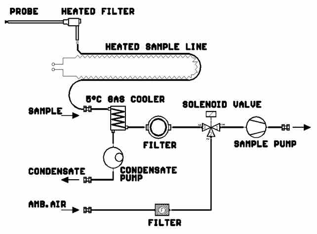
Extractive extraction method
In this method, according to the shape, the sample is absorbed by the sampler with the help of a suction pump from the desired environment. After passing through the path adjacent to the heater (Heated Line) and then passing through the cooler (Cooler) up to 5 ° C, it reaches the sensor or the most important and valuable part of the analyzer and there in various ways mentioned Is measured. Of course, it should be noted that in industrial environments, due to constant proximity analyzer Infrared detectors (in terms of durability, high accuracy and stability, as well as reasonable cost) are commonly used with the desired gases.
Block diagram of the path of gas passage into analyzer You have seen. Gas enters the device from the inlet. The corresponding solenoids determine that the sample or calibration gas is transferred into the device. A pressure sensor checks the sample pressure and then the gas enters the Infrared Gas Filter Correlation Infrared GFC-IR sensor of the device. The light source is a filament that, when it reaches a certain temperature, emits a certain infrared wavelength spectrum. This light passes through a correlation wheel with perforated holes. It then passes through an optical filter window, which is a specific wavelength filter, and enters the sensor. The rotating disk rotates and light passes through the cavities in turn as follows:
– Blurred part of the Dark sector
– The second part, which is an empty hole, Measure sector
– The third part, which has a cell filled with the desired gases
As light passes through each of these three parts, a specific electrical signal is output from the detector:
– Blurred signal: When light hits the blurred part and can not enter the device sensor.
– Measurement signal: when the light passes through the empty part of the wheel and enters the cell where the sample gas is in contact. In this case, certain wavelengths of light are absorbed by the molecules of the desired gases and the intensity of light decreases in proportion to the concentration of gases.
Reference signal: When light first passes through a cell containing reference gas. At the same time, the wavelengths absorbed by the reference are completely absorbed and eliminated. No more adsorption occurs as it passes through the sample containing the sampled gas.
The light receiver is a PbSe sensor located below zero by a peltier element at a cold temperature of 30 ° C. The output signal of the detector is transmitted to the microprocessor part of the processor by analog-to-digital converter.
Absorption of infrared wavelength by different gases
The above signals are compared for each gas and the analyzer processor performs the necessary calculations to measure the gas.
The above method is called GFC-IR, which is approved by the US-EPA standard of the US regulatory agency.
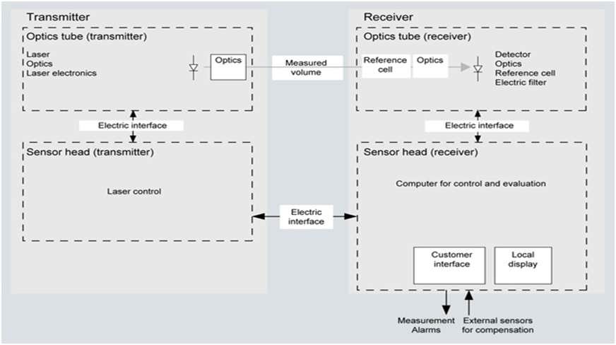
In-Situ Method
This method is often used in the control processes of systems such as O2 and Co gas measurements. Although similar to the Extractive type, it is also used to measure some gases for environmental cases, which is associated with limited gas diversity, and therefore this method is not recommended for measuring environmental cases. In these analyzers, the transmitter and receiver are used directly and in the vicinity of the gas, which has the advantage of short response time but difficult service defect in difficult conditions, such as at the top of columns.
In this type of analyzers, the humidity of the gas inside the column Gas measurement It is very effective. This humidity is measured by the humidity sensors installed in these analyzers and enter a coefficient in the calculation and measurement of gases, the final result of which can be seen after applying this coefficient.