
Torch control relay
What is a relay?
The relay is an electrical switch.
Many relays use an electric magnet to mechanically activate a switch, but other operating principles use solid-state relays.
Relays are used where current control is required by a single low-power signal or where multiple circuits are to be controlled by a single signal.
The first relays were used as amplifiers in remote telegraph circuits. They transmitted the signal received from one circuit to another.
Relays were also widely used in telephone exchanges and early computers for logic operations.
A type of relay that can control the high power required to directly control an electric motor or other force is called a contactor.
Solid state relays control power circuits using a semiconductor device for switching without any moving parts.
Relays with calibrated functional characteristics and sometimes several functional windings are used to protect electrical circuits from overload.
These capabilities in modern electrical power systems are performed by digital devices called “protective relays”.
Components of a relay
- Electric magnet
- A movable metal rod
- Fixed metal contact number
- Spring
The electric magnet consists of a metal core with a wire wrapped around it, and whenever the two magnet pins are connected to the power supply, the magnet starts working and absorbs the surrounding iron.
There is also an electric magnet in the relay, and the two ends of the coil of this electric magnet, which must be connected to the power supply, come out of the relay and form two of the bases of the relay.
In addition to these two pins, the relay has other pins.
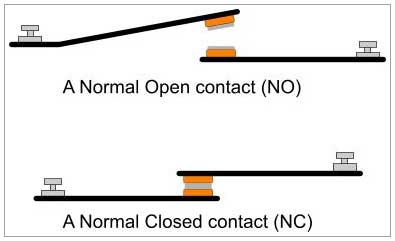
In the SPDT type, there are three other bases that are indicated by the names NO, NC and COM.
How the relay works
When the relay is not connected to the power supply, the COM terminal is connected to the NC terminal as follows:
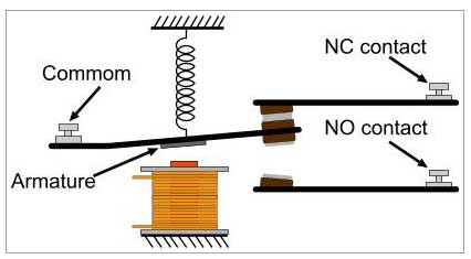
When the relay is connected to the power supply, in this case, an electric current passes through the coil that is wrapped around the electric magnet, and this electric current creates the property of a magnet and absorbs the iron parts.
Therefore, with the power connection, the COM pin, which was connected to the NC by default, is disconnected from the NC and connected to the NO.
The following figure summarizes how the relay works:

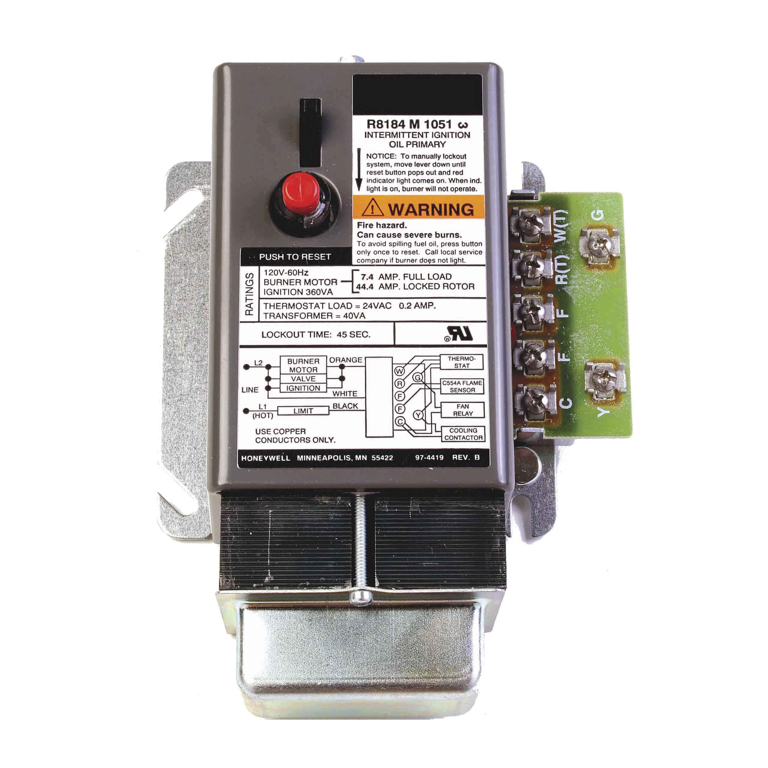
Torch relay
The function of the burner relay is to turn off the burner or boiler when it does not burn properly at start-up and the flame goes out during operation.
Modern furnaces and boilers use a cadmium cell sensor to detect the presence of flame and to ensure that in the absence of combustion inside the chamber, the fuel pump enters the combustion chamber.
The cell in charge of monitoring combustion is often connected by a wire to the burner relay, which is responsible for disconnecting and connecting the burner.
In fact, the way it works is that if the burner flame is off, the cadmium cell sends a signal to the burner relay and after 15 to 20 seconds the burner goes off.
Satronic torch control relay model 3-740 TMG
This burner control relay is able to control and monitor high performance environment for dual fuel burners (oil / gas).
This burner relay can be used for burners of any nominal grade as well as in air heaters.
Suitable flame detectors for it are: ionization probe, UV sensor and infrared detector.
According to French national law, a special version is available for combustion monitoring work.
Structural features
The control relay is transparent and flame resistant, enclosed in a shield and has a plastic sheath and includes:
- Engine at the same time as the “cam switch”
- The cam switch contains useful information and a color program indicator.
- The cam switch set controls the program sequence.
- Two DC relays and a protection relay in the common yoke
- The printed circuit board plug with the main transformer, LED display and electronic components is located at the bottom of the device and the flame detector selection switch is located at the bottom of the device.
The following key indicators and operational controls can be found on the front of the control box:
- Reset button that has a signal light for malfunction.
- Color program index
- Flame signal indicator
- Central connection screw
Technical Specifications
Flame detection
The following types of flame detectors can be used:
- Ionization electrode where the main source provides a neutral connection to ground. Suitable for gas burners (signal current from the flame can not be affected by ignition spark interference).
- 780 UVZ red UV sensor, suitable for gas, oil and dual fuel burners.
- Infrared detectors type 820IRD and 1020 for all types of flames.
- The flame signal amplifier is adjusted depending on the type of detector probe placed using the flame detector selection switch at the bottom of the device. If an IRD detector is used, the selection switch must be set to the ION position. Flame detection only works when the position of the selected switch is connected according to the type of detector probe. By optimizing the matching of the amplifier with the detector probe, much longer signal transmission distances with lower sensitivity to interference can be achieved.
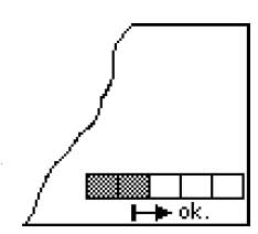
The flame signal flow indicator consists of a five-stage LED display that continuously displays the signal current.
Thus the flame signal strength indicator is always given.
Fluctuations in monitoring sensitivity can be detected in the early stages and appropriate corrective action can be taken.
If an 820 IRD or 920 IR detector is used, the flame signal current indicator on the control box is not.
In this case, the IRD indicator definitely indicates the strength of the flame signal.
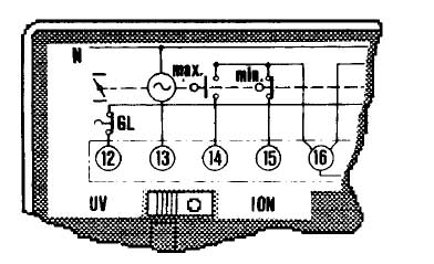
 Flame signal flow index