

An actuator is a set that is part of a control valve that provides the force and motion to operate a valve based on the received control signal. Actuators are actuators that require an energy source, which can be pneumatic, hydraulic, or electric. Thus, actuators essentially convert a pneumatic, hydraulic, or electrical signal into force and motion to move the valve toward closing or opening.
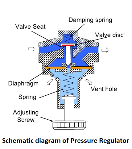
A simple design of a pneumatic actuator is shown below:

Classification of actuators
The actuator classification is a wide area to consider. There are several types of actuators for the operation of a control valve. A broad classification is given below
Classification of actuators based on motion
- Linear actuator
- Rotary actuator
Actuator classification based on design
- Manual actuator
- Diaphragm actuator
- Piston actuator
- Rack and pinion actuators
Actuator classification based on control source
- Pneumatic actuators
- Hydraulic actuators
- Electric (motor) actuators
- Electrohydraulic actuators
- Gas actuators
Actuator classification based on active ports
- single
- Double
Actuator classification based on control measures / failure performance
- Direct actuator (air to open / close with failure)
- Reverse actuator (air to close / not open)
- Type unlocked
Classification of actuators based on motion
The actuator receives a controlled energy source and converts it into motion, which can be linear or rotational. When actuators provide straight line motion for valve operation, they are called linear actuators. And when the control signal / energy goes to the actuator valve in a circular motion, it is called a rotating actuator. However, the linear actuator can also provide rotary output with the help of mechanical gears. And linear output can be achieved using rotary actuators such as mechanical gear / conversion assembly.
A simple diagram for a linear and rotary actuator is shown below:

Actuator classification based on design
Manual actuator
Manual actuators are those in which manual intervention is required to start a valve. No power source is required to replace manual actuators. These actuators can be used to control linear motion or rotary valves. The manual actuator uses a lever and gear mechanism to activate the valve movement. Manual actuators with different operating mechanisms are presented as follows:
- Manual actuators with handles
- Manual actuator with gearbox
- Manual actuator with sprocket / sprocket
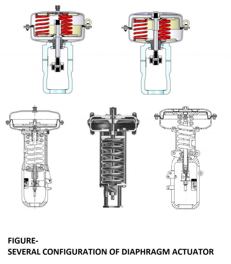
Diaphragm actuator
Diaphragm actuators are the most common type used extensively in industrial applications. A flexible diaphragm is placed between the two compartments. On one side of the diaphragm (with plate) is a spring assembly that holds the spring against the force created in the actuator pressure chamber to provide a safe position for failure. On the other side of the diaphragm, a controlled pressure (air supply) is applied, which leads to the positioning force of the stem for valve operation.
This type of actuator is called a single effect with a spring-loaded positioning force for linear motion. The actuator parts are designed in such a way that the actuator can be assembled in two safe positions (unsuccessful opening or closing). The main advantage of diaphragm actuator is its simplicity (design) which reduces maintenance and parts. The components of a typical diaphragm actuator are as follows:

There are several configurations of diaphragm actuators listed below:
Piston actuator
Piston actuators are another type of actuator that is widely used in industrial actuators. Uses a set of piston cylinders to create the final movement of the stem attached to the piston. The piston actuator has a configuration or spring return type or two actuators for valve operation. In the return spring to failure, the safe position can be open or closed. In a spring-return piston actuator, controlled pressure is applied to the other end of the piston. When a piston actuator is used for dual operation, controlled pressure is applied to both sides of the piston. When maximum pressure is applied to one end, fully open the valve. And when the maximum pressure is applied to the other end, close the valve completely. Piston actuators can operate pneumatically or hydraulically. The various parts of a typical reciprocating actuator are shown below:


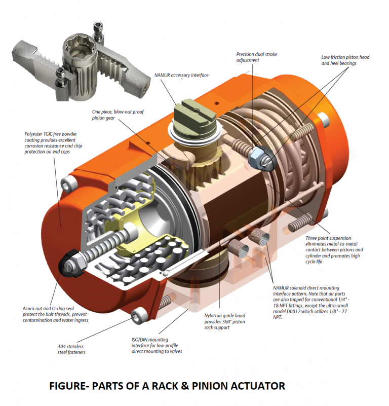
Rack and pinion actuators
Another type of actuator is the Rack & pinion actuator, which is mostly used for on and off applications (ie opening and closing valves) of quarter-turn valves such as butterfly valves, hubs, plugs and dampers are commonly used in industrial applications. “Rack and pinion” is a general term for a pair of gears that converts linear motion into rotational motion. A linear gear called a “rack” engages the teeth on a circular gear called a “pinion”. The linear force applied to the shelf causes the pinion to rotate. A simple structure of the actuator is shown below:

The Rack & Pinion mechanism uses two piston racks that move in opposite directions to ensure balanced forces on the pinion. Typically, pneumatic air pressure is used to feed the actuator. By applying pressure to the piston racks, the pinion can be rotated to the desired position. The bottom of the pinion is connected to the valve stem to open and close the valve by rotating the pinion. These operators are available in two structures:
Springback – Mechanical springback is for safe applications and can be assembled for Fail Close or Fail Open safety function.
Dual function – Dual actuators can be used for “position lock” safety function.
The different parts of a rack and pinion actuator are shown below
Actuator classification based on control source
Pneumatic actuators
Pneumatic actuators are simple mechanical devices that use a pneumatic signal or air pressure to move a valve mechanism, that is, a controlled pneumatic signal used to push a flexible diaphragm or a piston against a mechanical spring that results in mechanical or shock action. The key advantage of this design is that a pneumatic actuator can always reach a pre-defined safe condition, even after losing its primary power supply (air pressure or electrical signal to the control components). Today, the most important factor in distinguishing between pneumatic and electric actuators. Almost all actuators are designed from single-function spring-return actuators (as opposed to dual-function). Pneumatic actuators are widely used in refineries, petrochemicals, gas industries, pharmaceutical industries and fertilizer factories and so on.
A simple spring-loaded pneumatic actuator is shown in the figure.

Positive features of pneumatic actuators
- Pneumatic systems operate with air pressure, which is a safe fluid environment.
- All types of safe positions are available and can be configured with a pneumatic actuator.
- Pneumatic control equipment is widely available and relatively inexpensive.
- Pneumatic control systems can be configured to achieve a wide range of functions.
- Heavy-duty pneumatic actuators can be used to adjust applications.
- Pneumatic actuators allow you to operate at very high speeds.
- Pneumatic actuators are preferred for small to medium sized valves
Negative features of pneumatic actuators
- Pneumatic actuators are usually more expensive than equivalent torque electric actuators due to the use of control components such as solenoid valves, air filter regulators and other pneumatic precision instruments.
- Currently, pneumatic actuators are not easily integrated into electronic database management.
- As the size of the valve increases, so does the size of the pneumatic actuator, which slows down the valve.
- For the larger size of the actuator, larger pneumatic cylinders are used, which store a very high volume of air, which leads to higher energy costs for compressed air and higher weight on the pipe construction support.
Hydraulic actuators
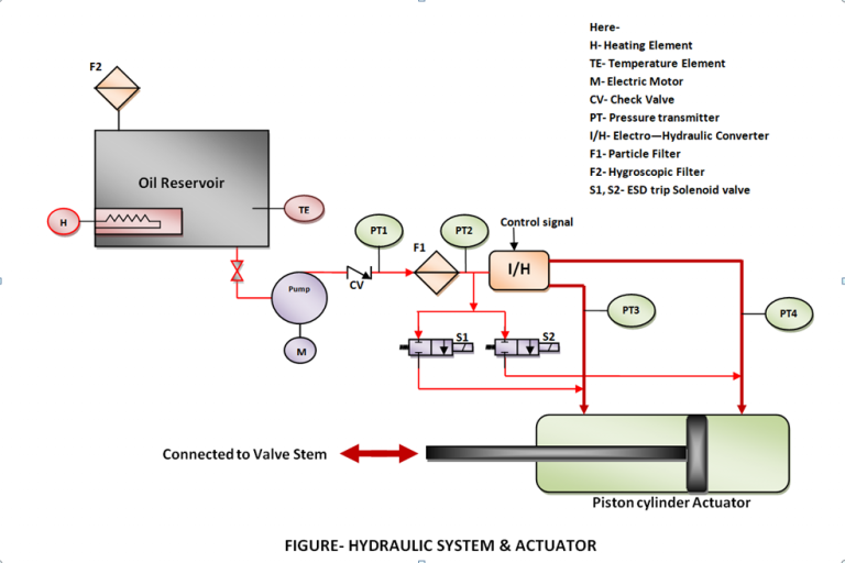
Hydraulic actuators are actuators that use hydraulic signal or fluid pressure (mostly oil) to move the valve mechanism, ie controlled hydraulic oil pressure is used to press the piston instead of the diaphragm against a mechanical spring or balancing pressure. Leads to mechanical action or valve impact. Therefore, high pressure hydraulic oil is applied to the piston to convert the fluid pressure into mechanical force. Therefore, it is necessary to design the piston (pressure rating) to apply high pressure. Here the hydraulic fluid (oil) used for the actuators is incompressible in nature and its lubricating property helps to overcome the friction problem of piston actuators. Hydraulic oil pressure is generated by an electric motor pump connected via an oil tank. Oil pressure can be used up to 400 bar (6000 PSI). Hydraulic actuators are used to apply a lot of force.
- oil tank
- Oil temperature monitoring system
- Bukhari
- Electric motor pump
- Pressure monitoring system in different stages
- Relief Willow
- Check Valves
- Particle filter and moisture absorbing filter
- Manual valves, solenoid valves
- I / H converter
- High pressure hose / pipe
- Piston Cylinder Set (Actuator)
A simple block diagram of the hydraulic system and actuator is given below:
A few tips to remind
Hydraulic actuators are primarily designed for the safe position of failure to lock the actuator, and the closed or failure position is achieved by the ESD opening function.
It should be noted that the release of fluid pressure in the open atmosphere is not possible, so the return of fluid to the reservoir path is provided in addition.
Hydraulic actuators are designed for both linear and rotary operation.
Since the fluid pressure is very high, periodic inspection of pipes and hoses at regular intervals is highly recommended.
Electric (motor) actuators MOV
Electric actuators or motor valves (MOVs) are used for large valve applications such as dampers. An electric motor is set up to control the position of the valve or to turn it on and off through the motor control circuit, which receives the control signal and produces the required rotation. Advances in engine design and engine control circuits have pushed motor valve (MOV) technology to the point where it now competes with older actuator technologies such as pneumatics to drive gas valves.
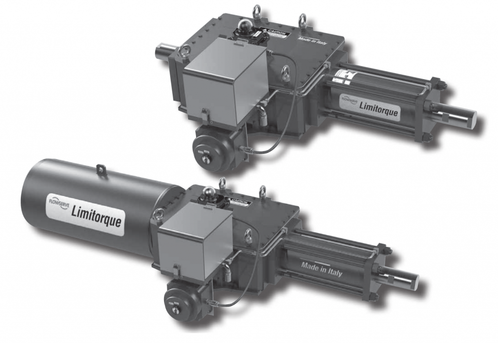
A simple diagram of a motorized valve is shown in the figure.

Negative features
- Electric actuators provide exceptional positioning accuracy to control or adjust valve performance.
- Because the electric actuator uses electrical power to operate, it is relatively inexpensive, easy to manage, and commonly available at most industrial sites.
- Electric actuators offer a high degree of process monitoring, data recording and information feedback.
- The cost of electric actuators is usually cheaper per unit of output torque / output.
- All necessary control functions such as open, closed position and throttle monitoring are part of electric actuators.
- Electric actuators significantly reduce control wiring costs by activating distributed control. They simplify control logic by integrating control commands and feedback into customer SCADA or DCS systems.
- As the need for torque and thrust increases, electric actuators weigh less and have smaller footprints than pneumatic actuators.
- Electric actuators may be combined with external gearboxes to produce very high amounts of thrust and torque.
Electrohydraulic Actuators ( EHA )
Electrohydraulic actuators are basically a type of hydraulic actuator with their own unique compression. These actuators are independent actuators with only electrical power. Electrohydraulic actuators eliminate the need for separate hydraulic pumps and pipes. In their original form, electrohydraulic actuators combine an electric actuator motor and pump assembly to compress a supply of hydraulic fluid, a hydraulic control group to control opening and / or closing operation, and a hydraulic cylinder with piston and actuator shaft. . valve. This initial design can be expanded to include a wide range of electrical or electronic control components and to provide steering and feedback capabilities equivalent to electric actuators. Position control is often integrated, meaning a force-balancing element with an overall electrical input signal (4 to 20 mA) and corresponding feedback through the spring board.
A simple structure of an electro-hydraulic actuator with its control function is shown as follows:

A flap nozzle system provides controlled pressure inside the two-acting hydraulic cylinder through a special high-pressure hydraulic pressure valve to the desired position of the valve stem. This results in a proportional relationship between the input signal and valve movement (stroke). Like an electromechanical actuator, it is possible to reverse the direction of motion and force. If a power plant has multiple electro-hydraulic actuators, a single central hydraulic unit is often used.
Positive features
- Very high actuator drift is achievable.
- Relatively high control rate (caressing speed) is possible.
- High stiffness (travel stiffness) reduces valve stem oscillations.
- Automatic failure position in case of auxiliary energy loss.
Negative features
- Very heavy, extensive construction, expensive.
- In most cases, not every installation position is suitable.
- Explosion protection can only be achieved at a high cost.
- Not suitable for very high and low temperatures.
- Sensitive to harsh service conditions, frequent maintenance required
Gas actuators
Gas actuators are specifically designed to work with high pressure natural gas or any high pressure pneumatic or hydraulic fluid. These actuators are ideal for pipeline applications where there is no external source of actuator power and offer a robust, heavy-duty design with industry-leading maintenance intervals. This makes them the actuator of choice for installation in remote or unmanned installations. There are two types of gas actuators:
- Direct gas
In this configuration, the pipeline gas is directed directly to the actuator power cylinder.
- Gas -over – oil
This design pumps the pipeline gas into the tank used to pressurize the hydraulic fluid, which is then fed to the pipe actuator power cylinder.
A simple diagram of gas actuators is given below:
Advantages of gas actuators
- Gas actuators do not need an external power supply. The actuator power is supplied by the pipeline product and is always available for use.
- Pipeline pressure supports the use of large actuators in any environment and allows separation or safe operation via mechanical springs (in direct gas versions) or stored hydraulic pressure (in gas models over oil).
- Direct gas actuators weigh less than oil models and have lower initial capital costs because they do not require a tank or hydraulic control. They also have simpler control circuits because they only work on the gas source.
- Gas actuators have the advantage of using clean hydraulic fluid in the actuator power cylinder more than oil. This is especially noticeable in the case of linear gases with heavy particles or corrosive contents.
- Despite the shelf life benefits of gas over oil, markets that use gas-fired actuators are moving to direct gas due to improved anti-corrosion treatments.
Disadvantages of gas actuators
- The main drawbacks of gas actuators are tied to their main advantage. Using the pipeline product leads to a relative “waste” of the product.
- More importantly, every blow of the pipeline gas valve discharges into the atmosphere with negative environmental effects. In these cases, an efficient torque mechanism and a smaller cylinder volume per torque unit are important to reduce the amount of exhaust gas.
Actuator classification based on active ports
Single Action
In a one-act actuator, control pressure is applied to an actuator inlet port to operate / open the valve. And the closing of the valve is determined by the stored energy of the spring. To close the valve, the applied pressure is proportionally reduced and driven by the return / release of the spring. There are two possible types of operation (without the use of air lock relay) –
- Direct actuator (press to open / close with failure)
- Reverse actuator (enter to close / do not open)
When the control pressure applied to the actuator is used to open the valve and the energy at the return of the spring for the safe closing of the valve is called the direct actuator. In direct actuator control, signal failure causes the valve to close as a safe act of failure. When the control pressure applied to the actuator is used to close the valve and the energy at the return of the spring is used to open the valve safely, it is called the reverse actuator. In reverse actuator control, signal failure causes the valve to open as a safe act of failure.
However, the Fail to Lock position can be achieved by installing an air lock relay, so that when the control signal fails, the pressure applied to the actuator must be constant to hold / lock the valve in the same position.
Double Action
In double action actuator, there are two ports for applying control pressure, in which the controlled pressure in one port is used to open the valve and the controlled pressure in the other port is used to move the valve towards closing. Mostly dual-action actuators are not locked. However, failure valve opening and closing conditions can also be achieved by using control valve accessories such as valve and solenoid positioners.
Actuator classification based on control measures / failure performance
- Direct actuator (air to open / close with failure)
- Reverse actuator (air to close / not open)
- Type lock failed
When the control pressure applied to the actuator is used to open the valve and the energy at the return of the spring for the safe closing of the valve is called the direct actuator. In direct actuator control, signal failure causes the valve to close as a safe act of failure.
When the control pressure applied to the actuator is used to close the valve and the energy at the return of the spring is used to open the valve safely, it is called the reverse actuator. In reverse actuator control, signal failure causes the valve to open as a safe act of failure.
Fail to Lock actuators are those that hold / lock the valve position in the same position when a signal failure occurs. In single actuator, air locking relay can be installed and in dual-function actuator, non-locking can be achieved by keeping the control pressure constant in both actuator ports or by releasing pressure in both ports .