


In the figure above, the temperature measuring circuit consists of a thermocouple connected directly to the temperature transmitter. Hot and cold connections can be placed anywhere to measure the temperature difference between the two connections. In most cases, we need to monitor the temperature rise of the equipment to ensure safe operation. Increasing the temperature of a device is the operating temperature using the ambient or room temperature as a reference. To achieve this, the hot connection is located in the device or its connection point and the cold connection point is in the meter or transmitter as shown in the figure below.

Advantages and disadvantages of thermocouples
Advantages:
- Most transformers use thermocouples. The hot connection point is inside the transformer oil and the cold connection point is inside the meter installed on the outside. With this simple and uneven installation, the meter directly reads the air temperature above the ambient temperature.
- In general, thermocouples are used exclusively around turbine halls due to their rugged construction and low cost.
- A thermocouple is able to measure a wider temperature range than RTD.
Disadvantages:
- If the thermocouple is a short distance from the measuring device, expensive thermometer wires or compensating cables should be used.
- Thermocouples are not used in areas with high radiation fields (for example, in a reactor room). Radioactive radiation (for example, beta radiation from neutron activation) causes voltage across the thermocouple wires. Since the signal from the thermocouple is also a voltage, the resulting voltage causes an error in the output of the temperature transmitter.
- Thermocouples are slower to react than RTDs
- If the remote control logic is located and temperature transmitters (mV to mA converters) are used, the power supply will definitely cause faulty readings.
Failure modes:
- The open circuit in the thermocouple detector means that there is no way to flow, so it will cause low temperature reading (off-scale).
- A short circuit in the thermocouple detector will also cause the temperature to read low because it creates a leakage current path to the ground and a smaller measured voltage.
Thermal thermowells
The process environment in which temperature monitoring is required is often not only hot but also pressurized and possibly chemically corrosive or radioactive. To facilitate the removal of temperature sensors (RTD and TC), to check or replace and provide mechanical protection, the sensors are usually mounted inside thermal thermowells (Figure below)

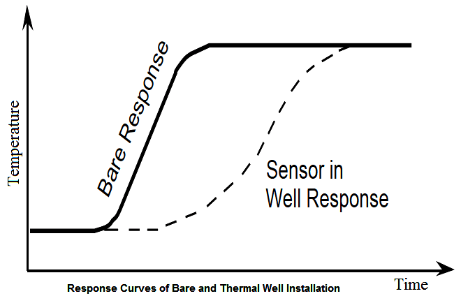
A thermal thermowell is actually a hollow metal tube with one end sealed. It is usually installed in pipe work. The sensor is inserted into it and makes contact with the sealed end. The problem with thermal thermowells is that they take a long time to respond because heat must be transferred to the sensor through the thermowell. An example of a temperature response for naked and thermal sensors is shown in the figure below. However, minimizing the air space between the sensor and the thermowell can reduce this thermal delay.